
Thu Jan 18 11:03:21 2018
Project Directory: /scratch/sft/tam/IDEAS/East_River/GIS_workflow
New link to: /scratch/sft/tam/IDEAS/East_River/Copper_Creek
Steps for DEM to ATS Workflow:
INPUT DATA: Define and Process Input Data
SETUP: Define Spacing, Layers, and Boundaries
TOP SURFACE: Create Top surface triangulation and interpolate DEM
EXTRUDE INTO 3D: Generate Mesh Layers and stack into 3D Element mesh
MODEL SETUP: Write 3D Mesh and Boundary face sets to Exodus file.
All diretories include a compressed tar file with:
    prism_single_fs3.exo - single column with 3 facesets
    prism_fs7.exo - full mesh with 7 facesets (bottom,top,right,back,left,outlets)
    prism_fs3.exo - full mesh with 3 facesets (bottom,top,sides)
    README.txt

/scratch/sft/tam/IDEAS/East_River/Copper_Creek

Smooth 50m Triangulation

    Feb 12 lagrit_tri_50m_v1
    lagrit_tri_50m_v1/prism_fs7.exo nodes: 63822    cells:  103750  sm_50m_v1.tar.gz  (11M)


    Feb 12 lagrit_tri_50m_v2
    lagrit_tri_50m_v2/prism_fs7.exo nodes: 180829   cells:  332000  sm_50m_v2.tar.gz  (18M)


Smooth 20m - 150m Triangulation Refined to River Outlet, Coarse away from river

    Jan 17 V1 Smooth 20-0150m
    lagrit_tri_20-150m_v1/prism_fs7.exo  nodes:   33618  cells:   54100  sm_20-150m_v1.tar.gz  (2.6M)


    Jan 17 V2 Smooth 20-150m
    lagrit_tri_20-150m_v2/prism_fs7.exo  nodes:   95251  cells:  173120  sm_20-150m_v2.tar.gz  (7M)


Stair-Step 20m Uniform from Quad grid

    Jan 16 V1 Uniform 20m
    lagrit_uniform_20m/prism_fs7.exo     nodes:  423534  cells:  696980  uni_20m_v1.tar.gz  (17M)


    Jan 17 V2 Uniform 20m
    lagrit_uniform_20m_v2/prism_fs7.exo  nodes: 1200013  cells: 2230336  uni_20m_v2.tar.gz  (44M)
All Watershed Mesh and DEM images
|
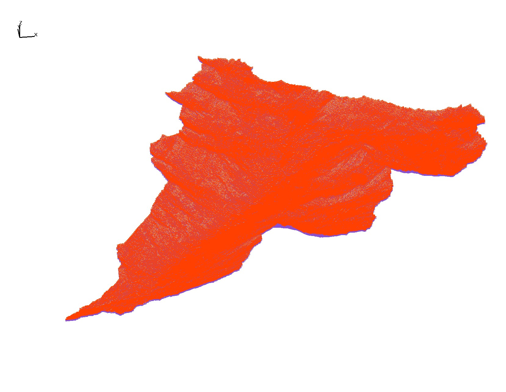
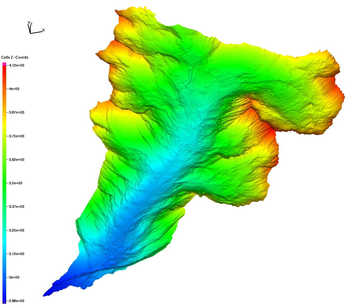
East River DEM with NULLS removed
|
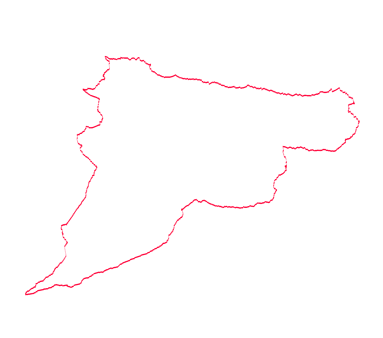
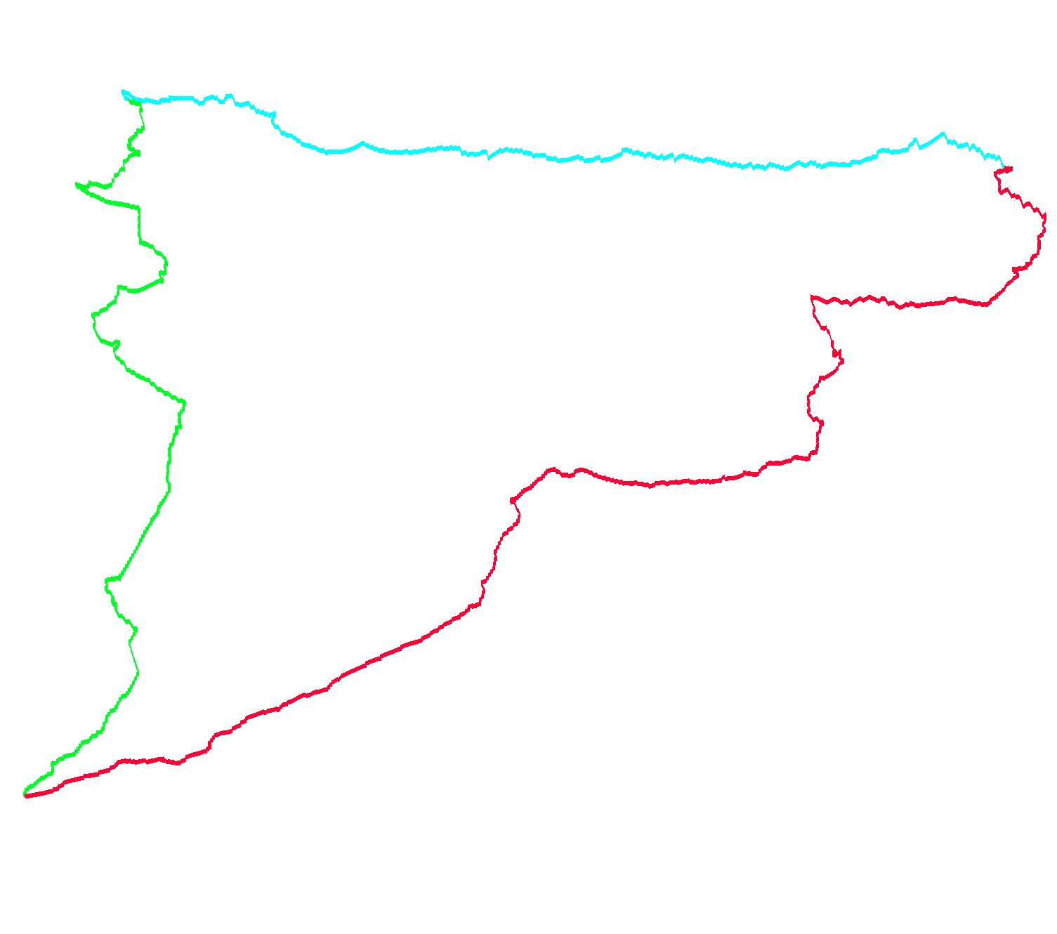
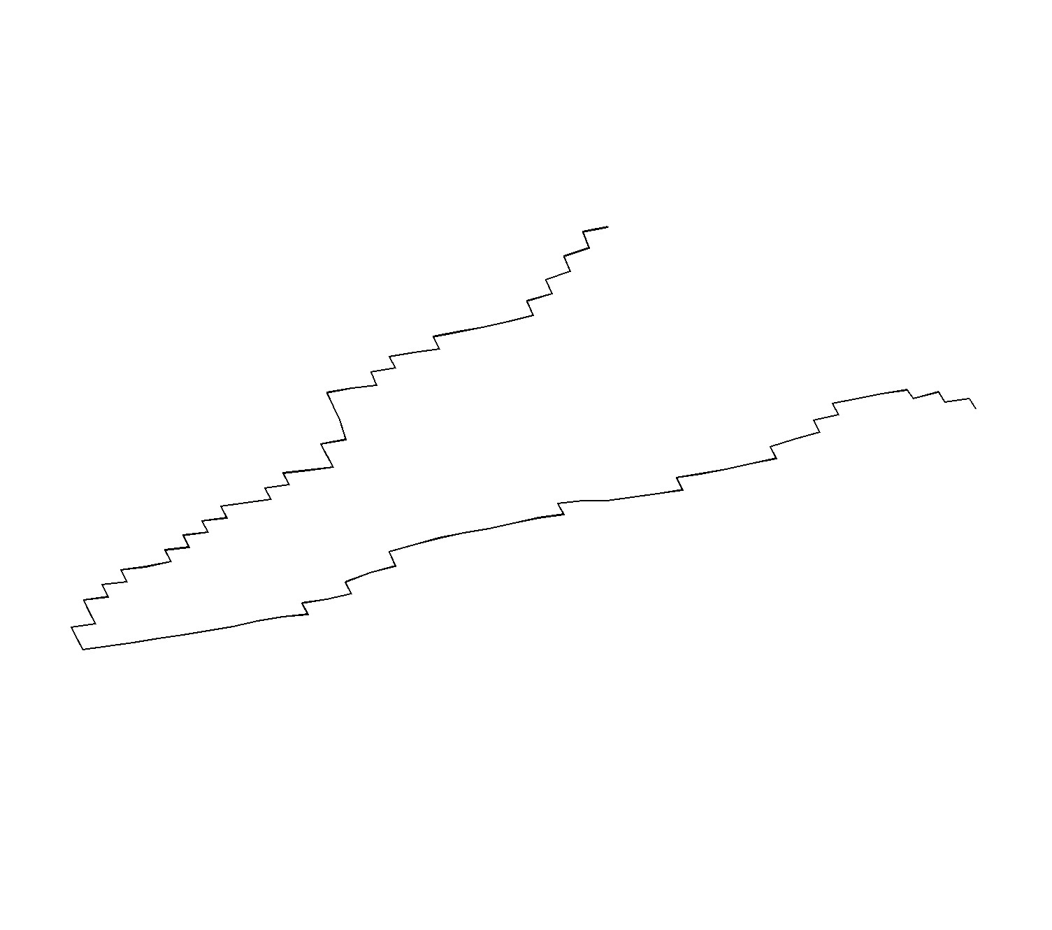
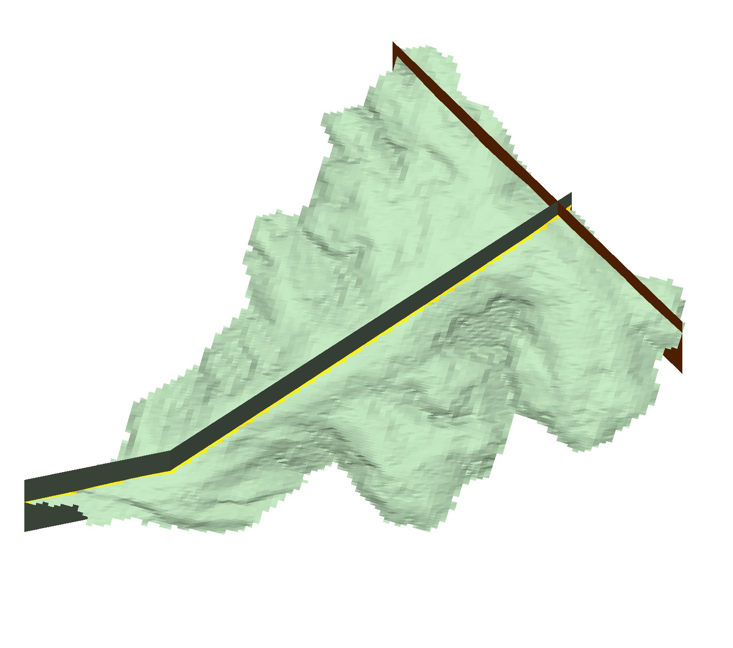
Lines for boundary sides
|
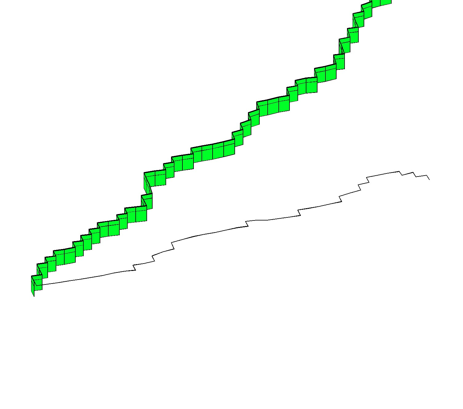
Lines into planes for regions
|
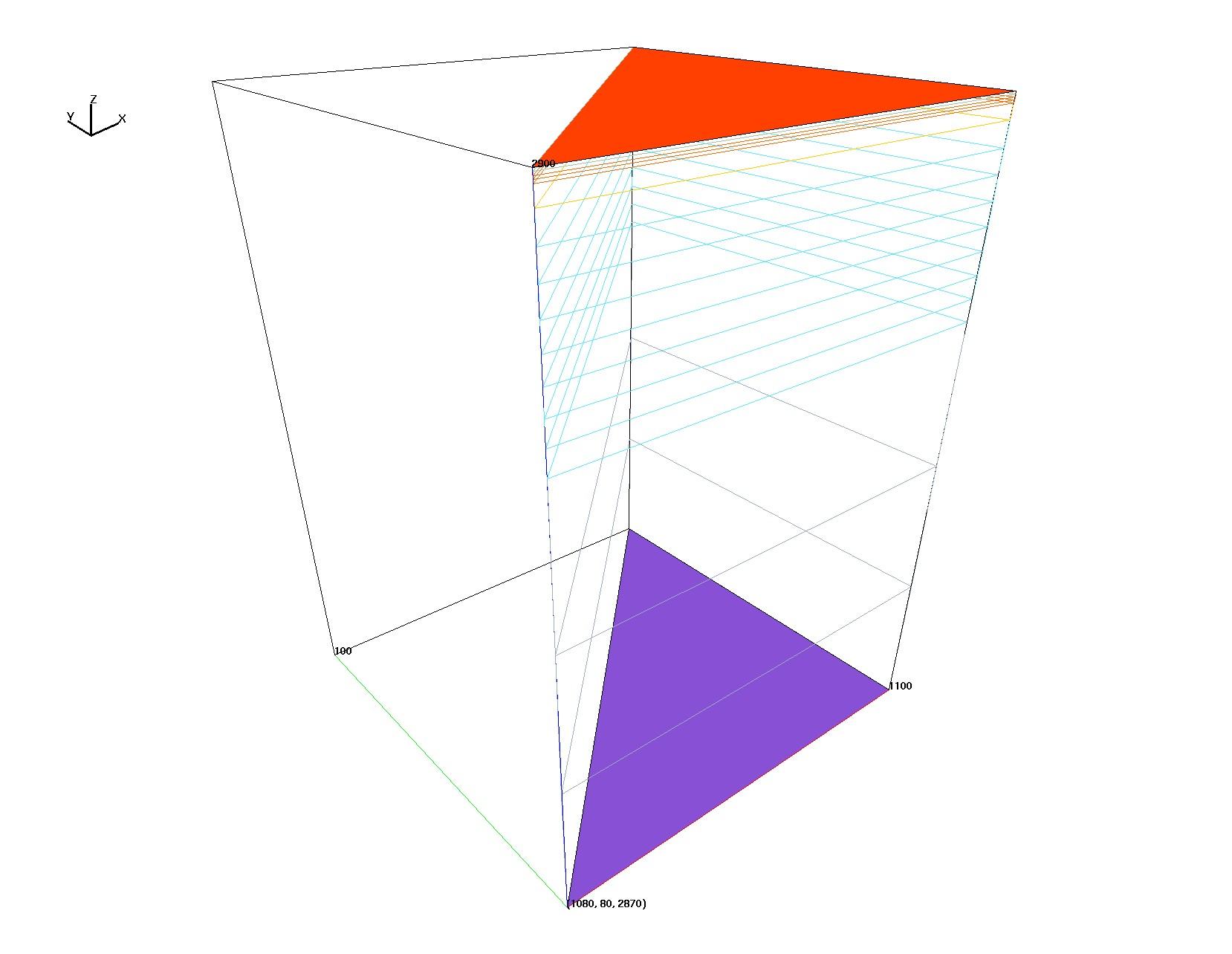
V1 5 Layers single cell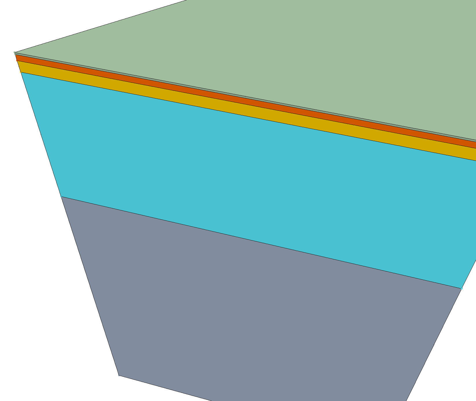
|
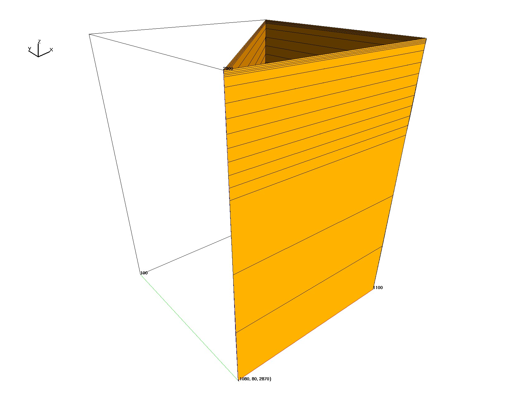
V2 5 Layers with multiple cells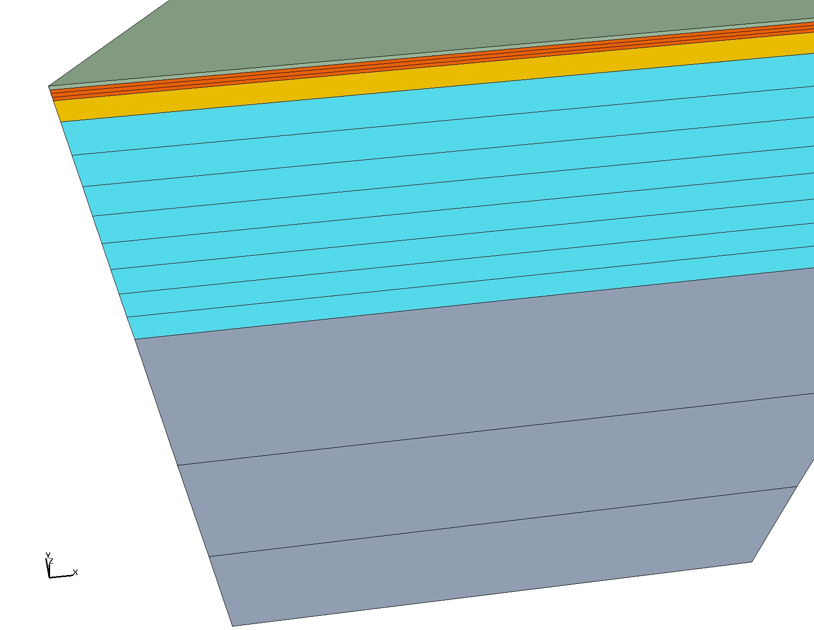
|
V1 Material layers are ordered from top = 1 to bottom = 5. Each layer is 1 cell thickness (thickness = dz). Layer 1: dz = 0.1, sublayers = 0 Layer 2: dz = 0.3, sublayers = 0 Layer 3: dz = 0.6, sublayers = 0 Layer 4: dz = 8.0, sublayers = 0 Layer 5: dz = 21.0, sublayers = 0 Total depth = 30 meters |
V2 Material layers are ordered from top = 1 to bottom = 5. Layer 1: dz = 0.1, sublayers = 0, cells 1 Layer 2: dz = 0.1, sublayers = 2, cells 3 Layer 3: dz = 0.6, sublayers = 0, cells 1 Layer 4: dz = 1.0, sublayers = 7, cells 8 Layer 5: dz = 7.0, sublayers = 2, cells 3 Total depth = 30 meters |
Requires boundary polygon at uniform spacing.
LaGriT is used to triangulate and smooth with coarse edge lengths away from river.
Refinement of 20m is added at elevations lower than 3000m which is at river outlet.
Quality measurements include aratio (1=all angles equal), min edges, max edges.
poly_50m_bndry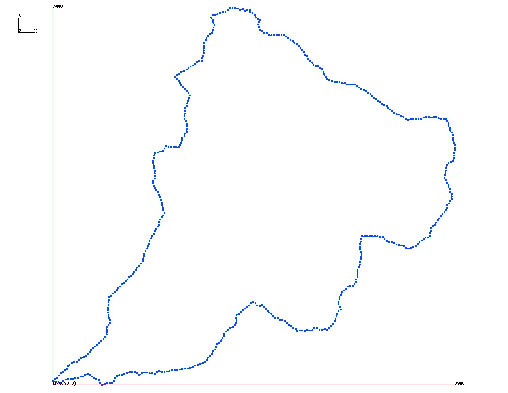
|
poly_50m_triangulate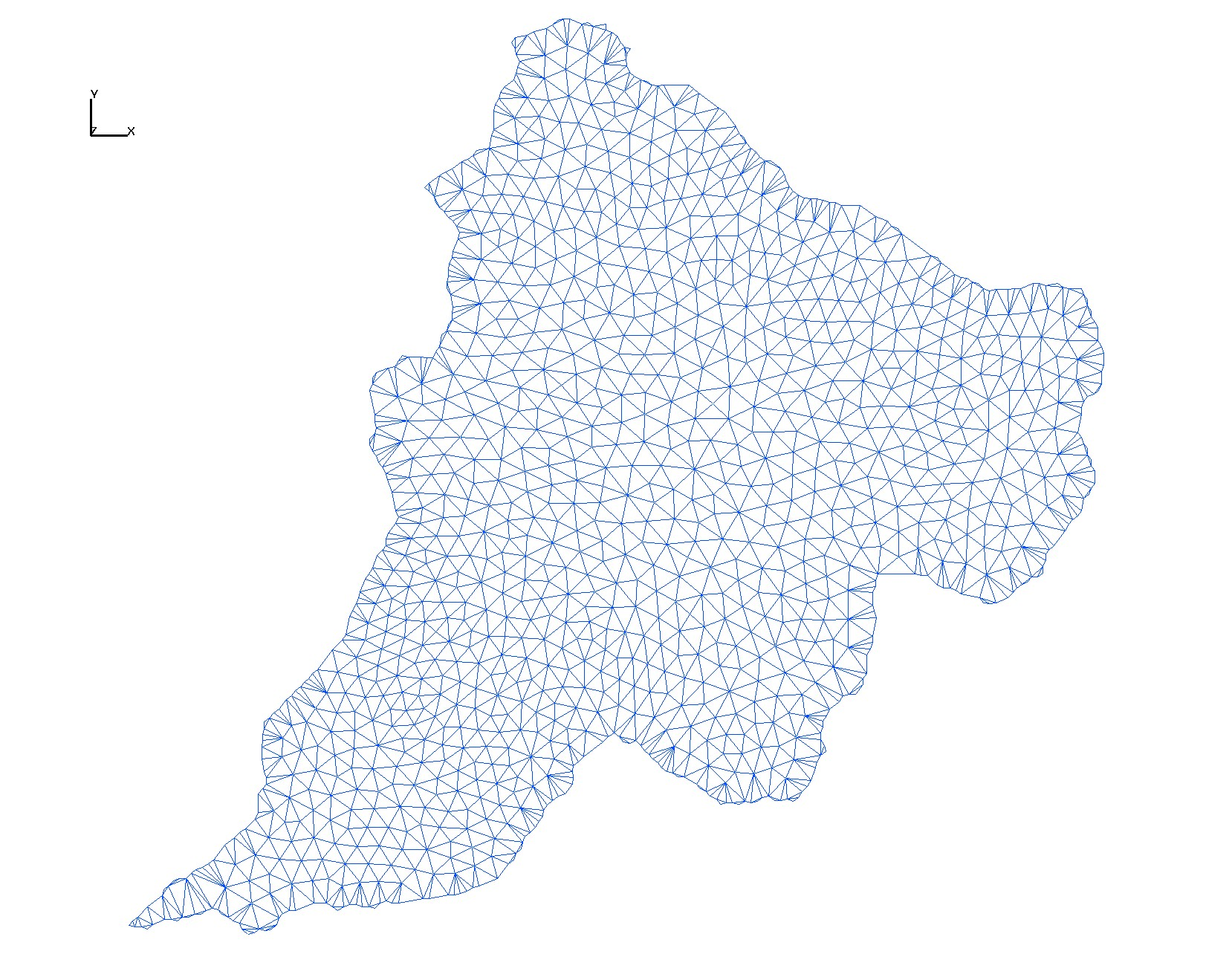
|
sm_20-150m_elev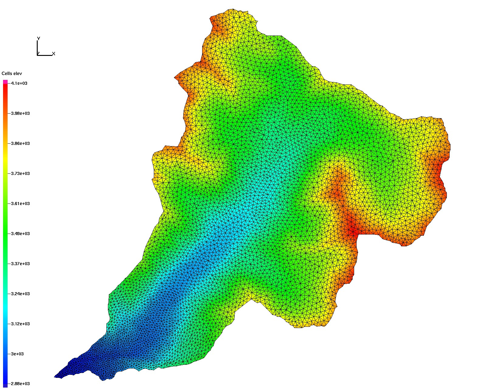
|
sm_20-150m_aratio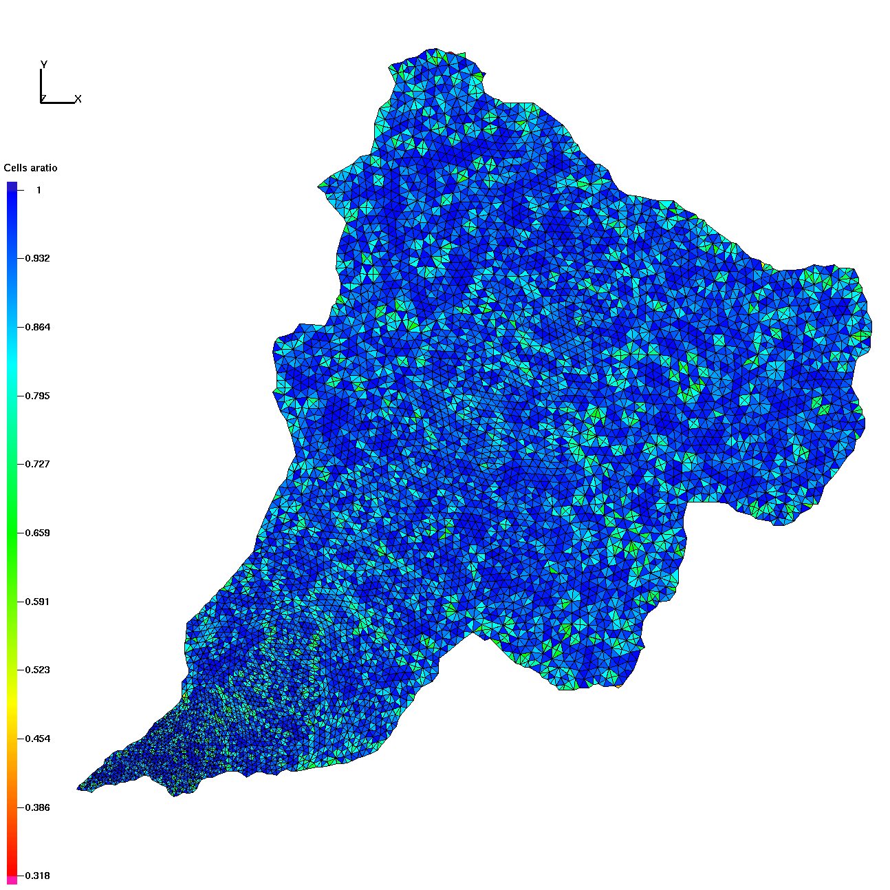
|
sm_20-150m_emax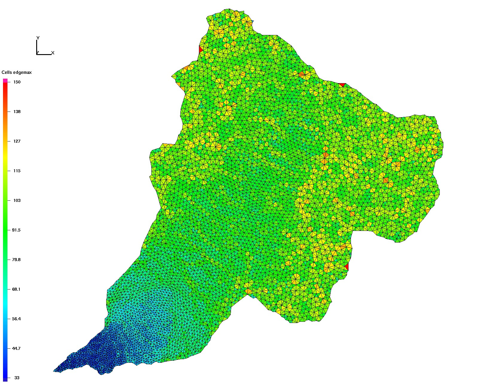
|
sm_20-150m_emin
|
sm_50m_aratio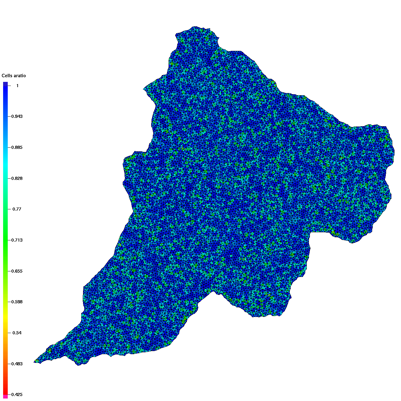
|
sm_50m_emax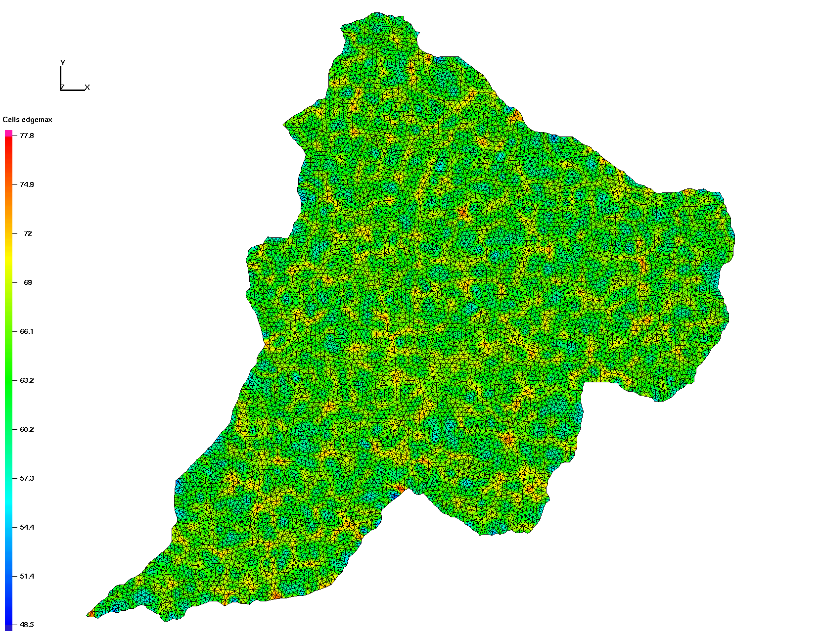
|
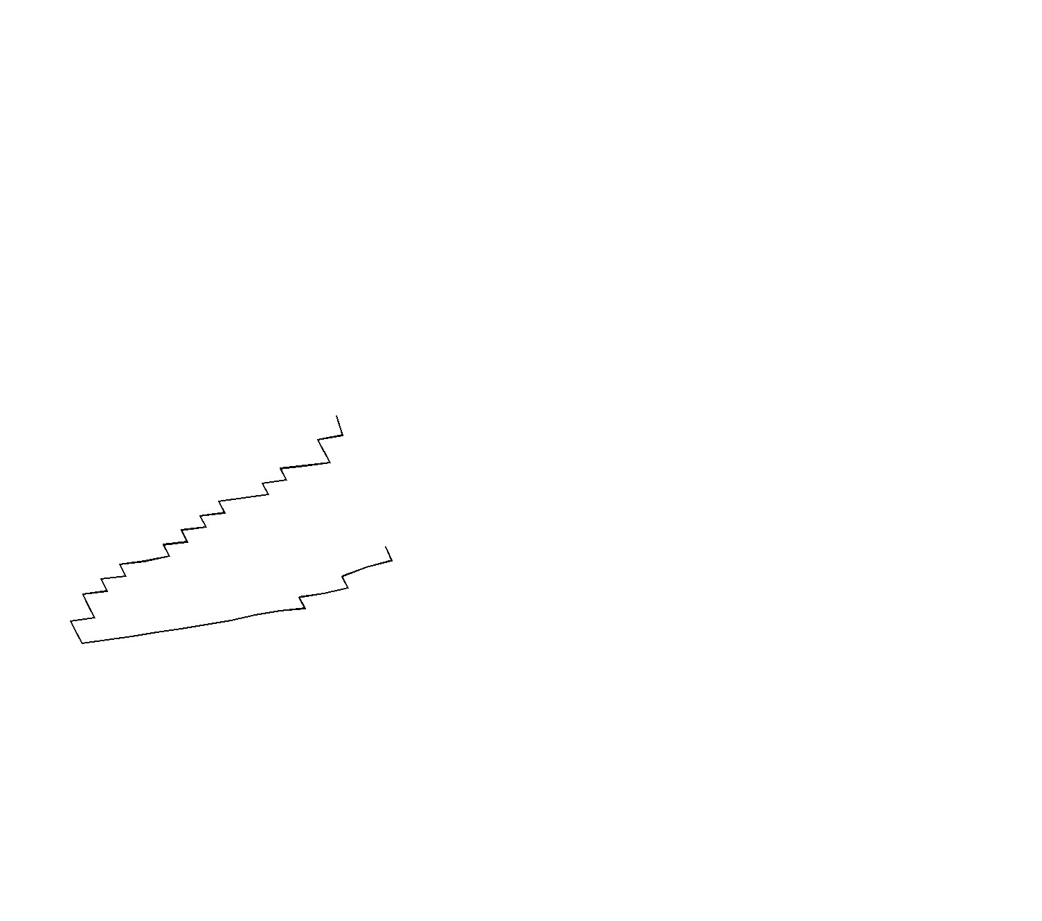
sm_50m_outlet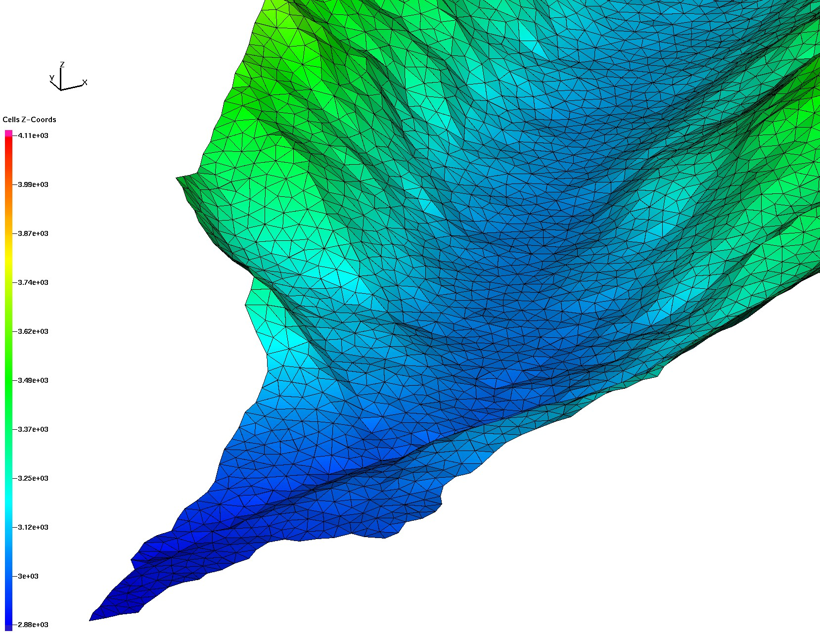
|
tri_elev_full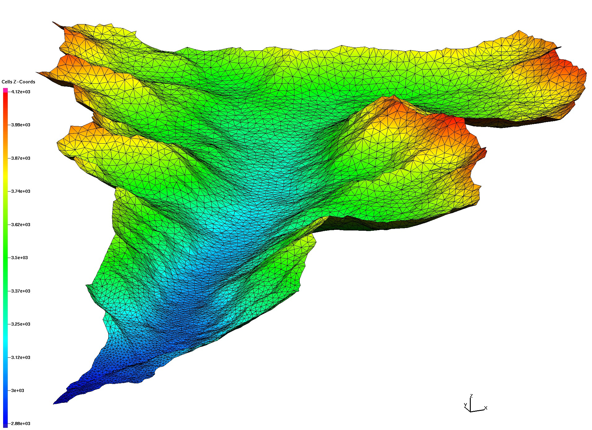
|
tri_river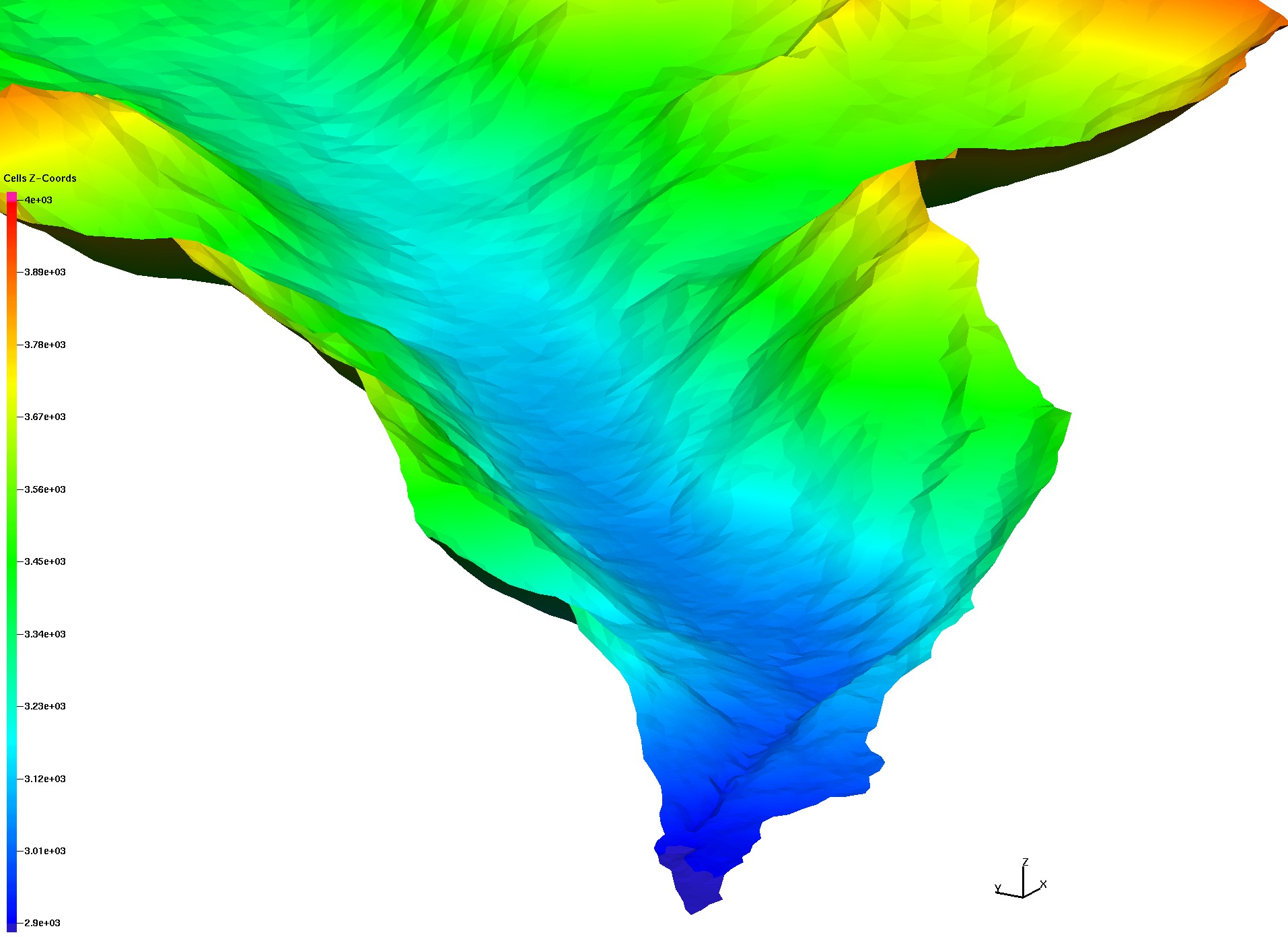
|
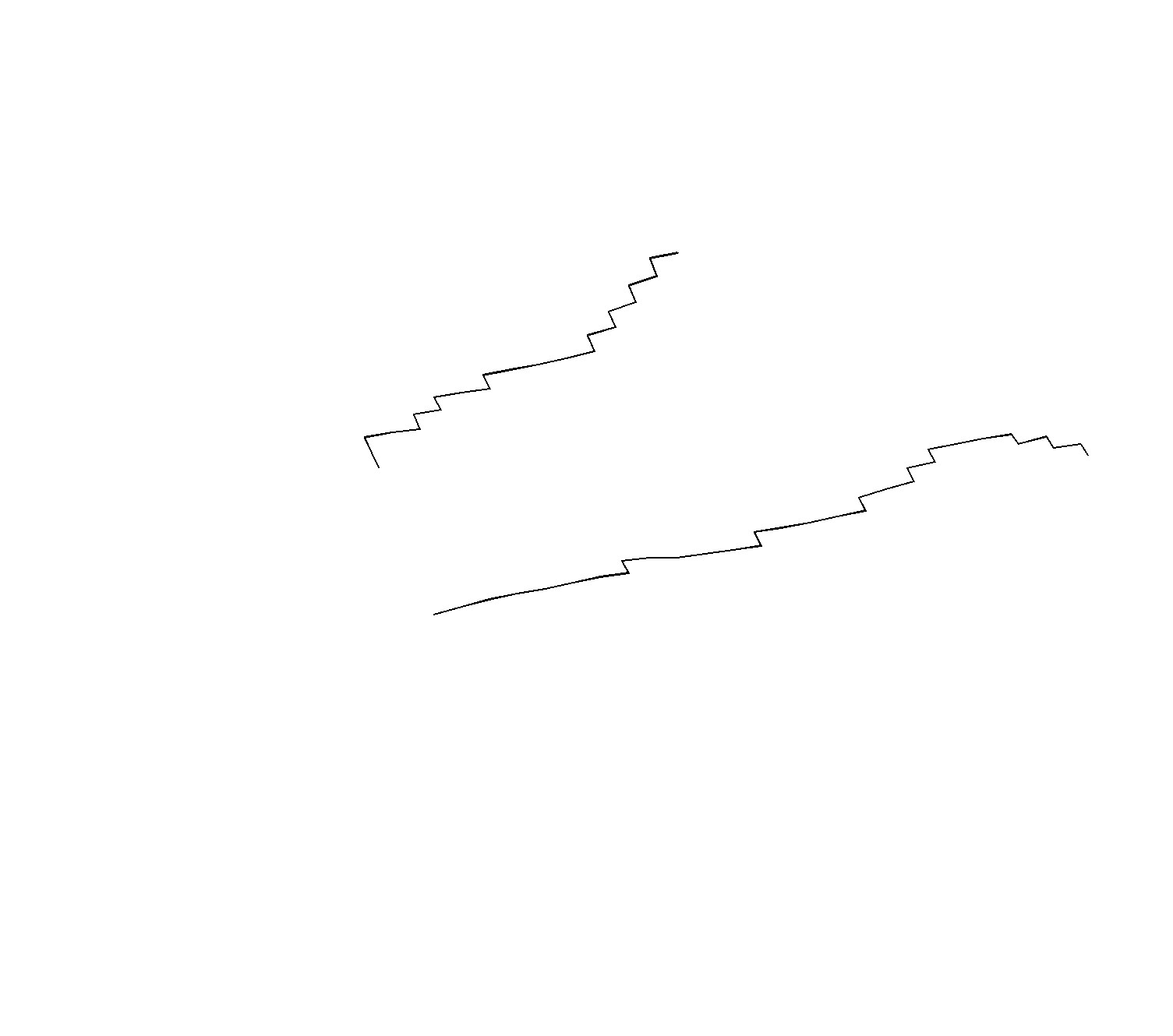
sm_20-150m_outlet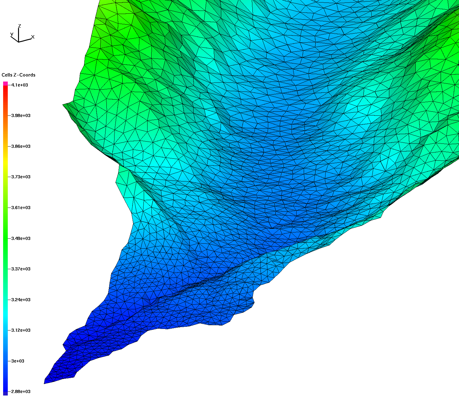
|
Create a quad mesh of uniform 20m spacing, convert each quad to 2 triangles.
Interpolate the DEM on to the grid and remove outside cells.
Quality measurements include aratio (1=all angles equal), min edges, max edges.
Note these uniform right angle triangles have edges stretched by the Z elevation.
uniform_quad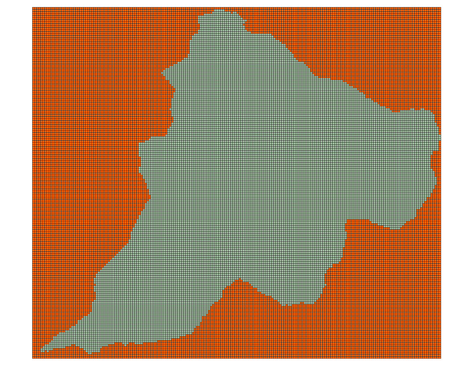
|
uniform_quad2tri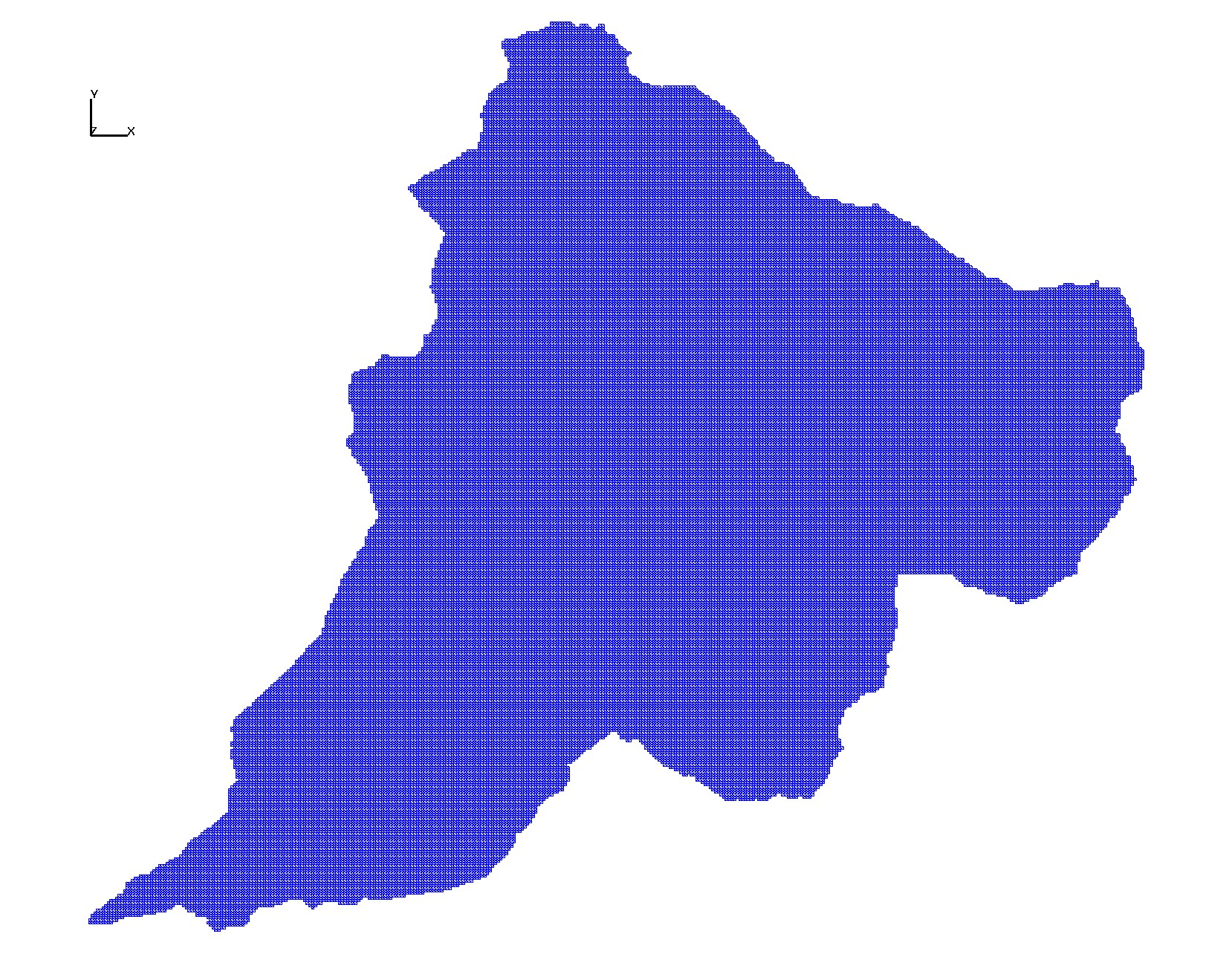
|
uniform_elev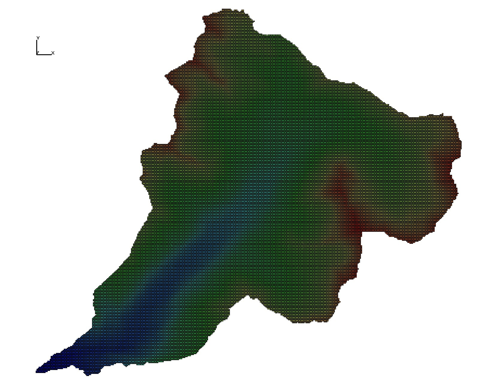
|
uniform_aratio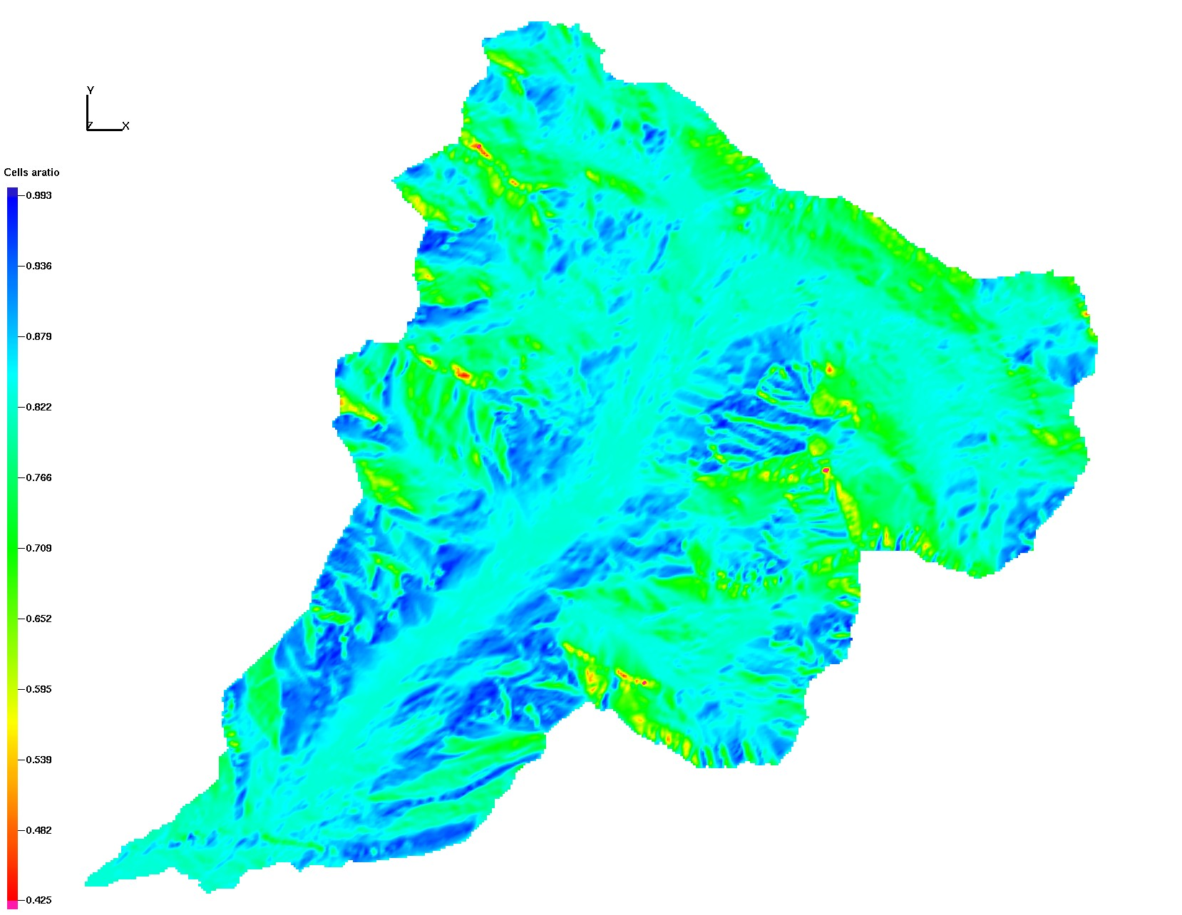
|
uniform_emax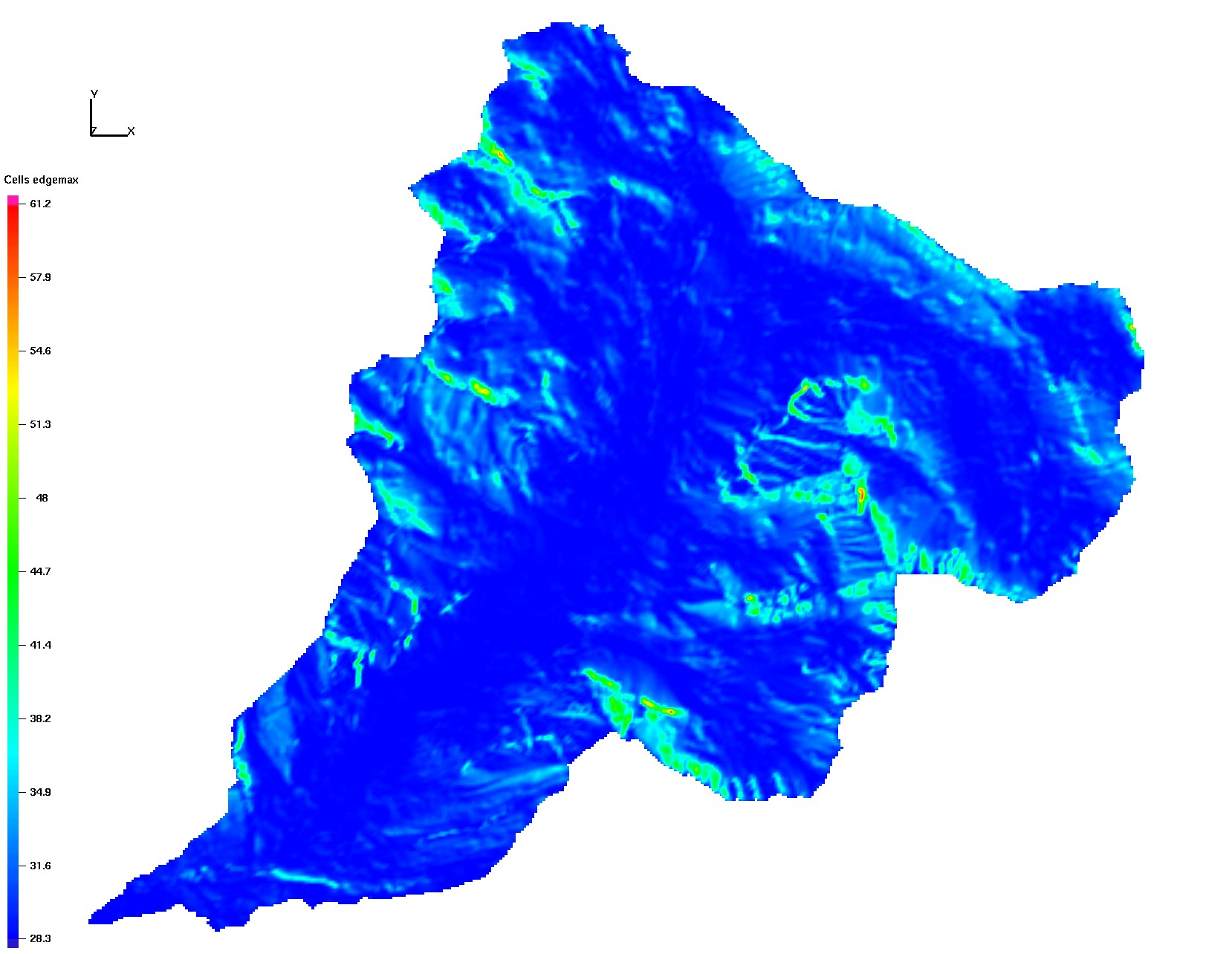
|
uniform_emin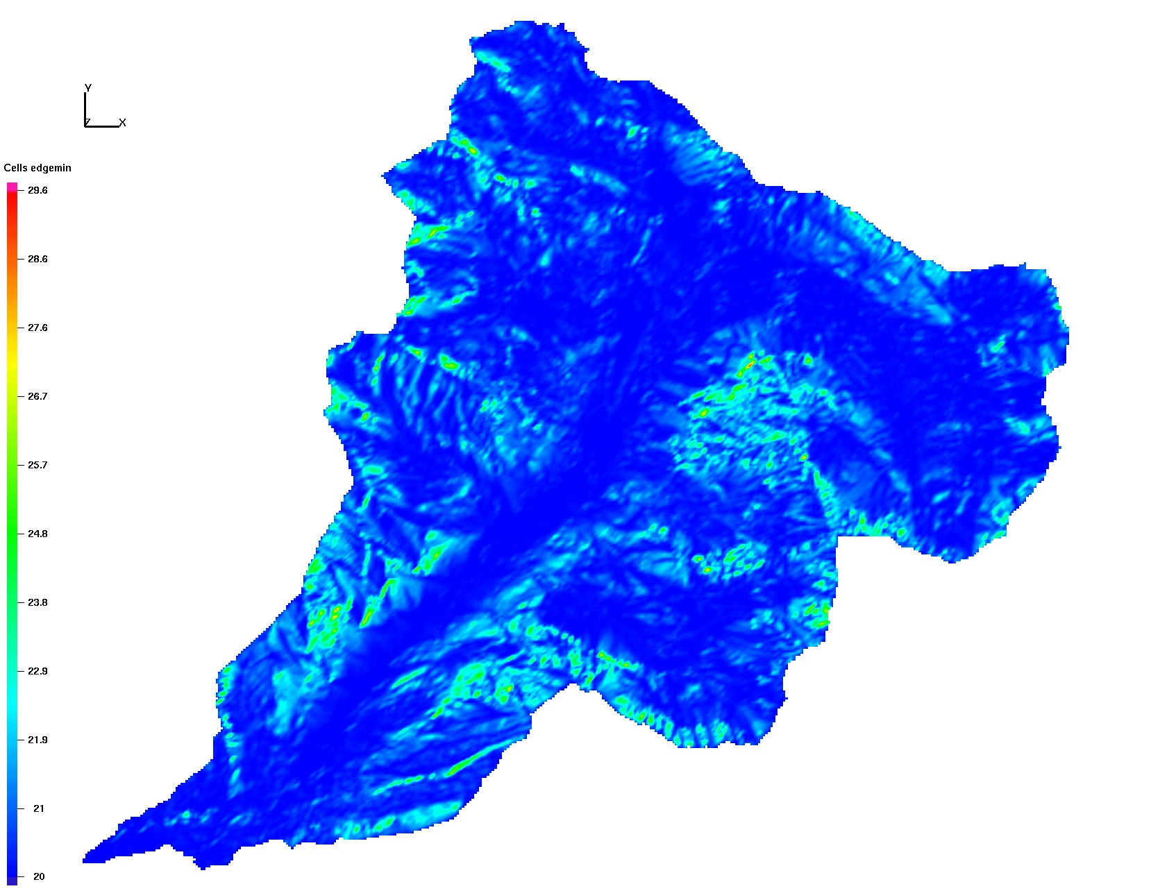
|
uniform_full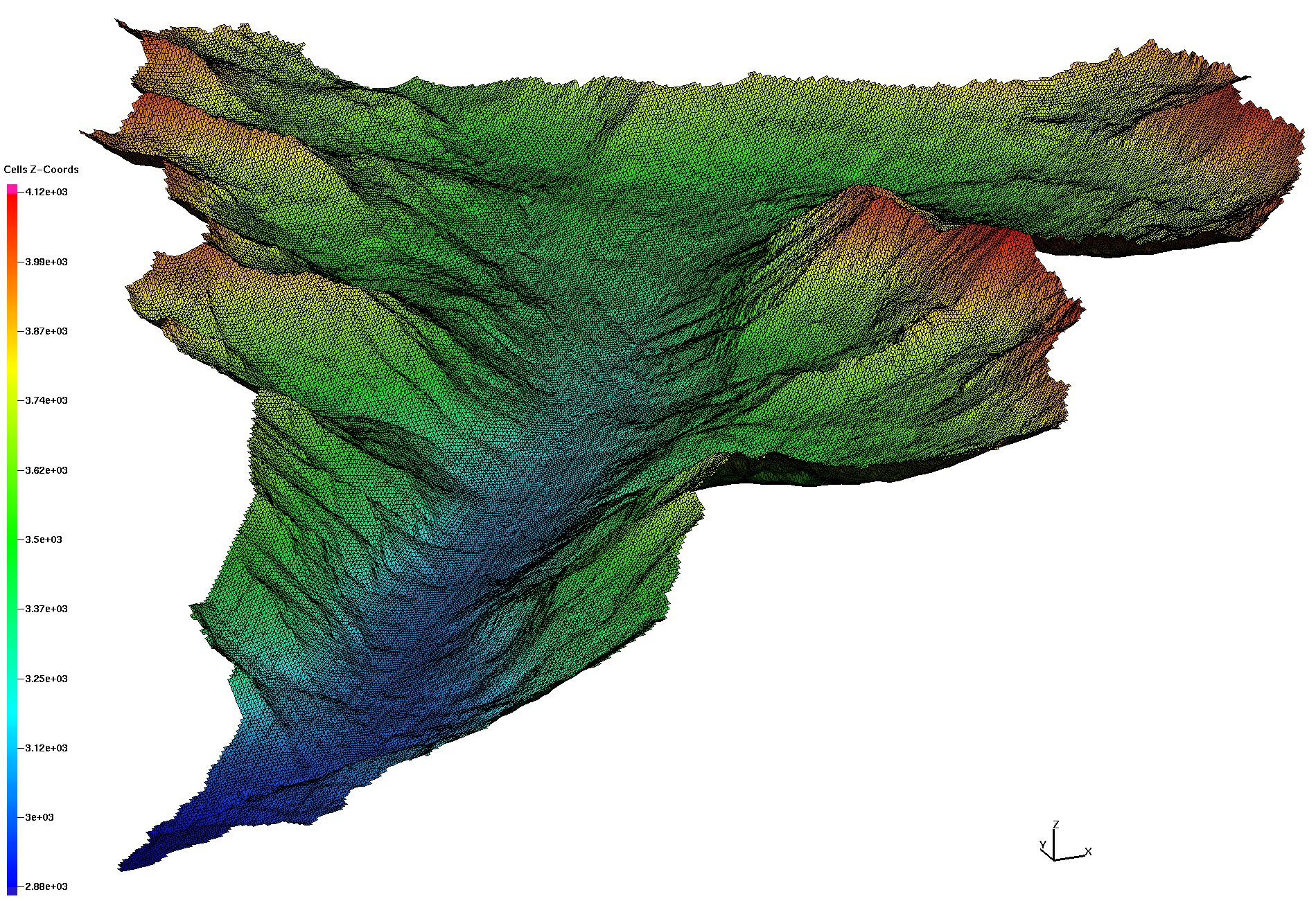
|
uniform_river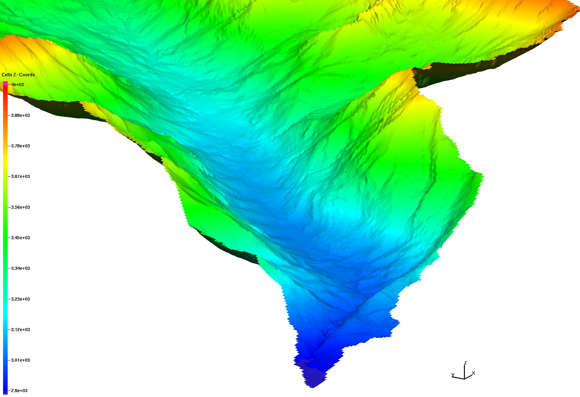
|
uniform_outlet
|
Use LaGriT to create layers from the top triangulation by translating to depth.
Stack layers and add sublayers as indicated.
Connect stacked layers into a prism mesh.
smooth_mesh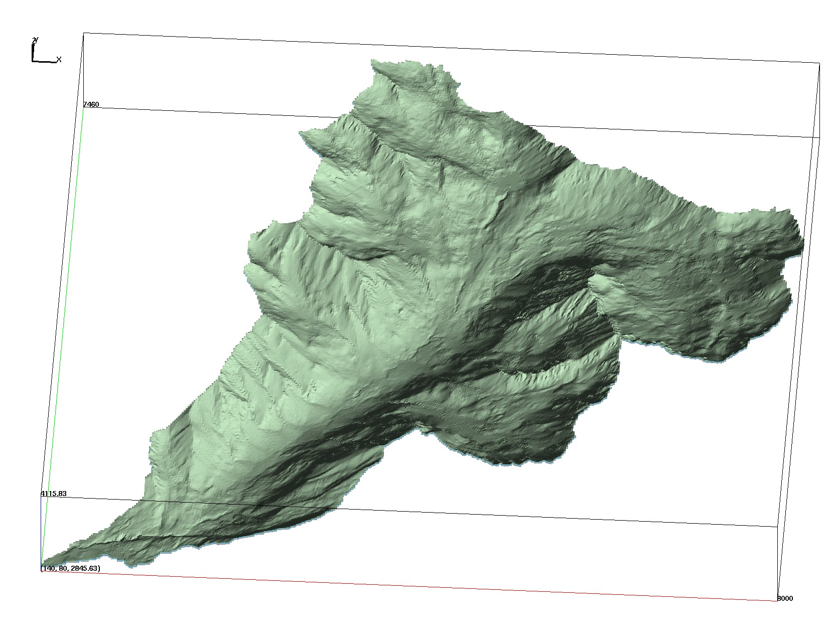
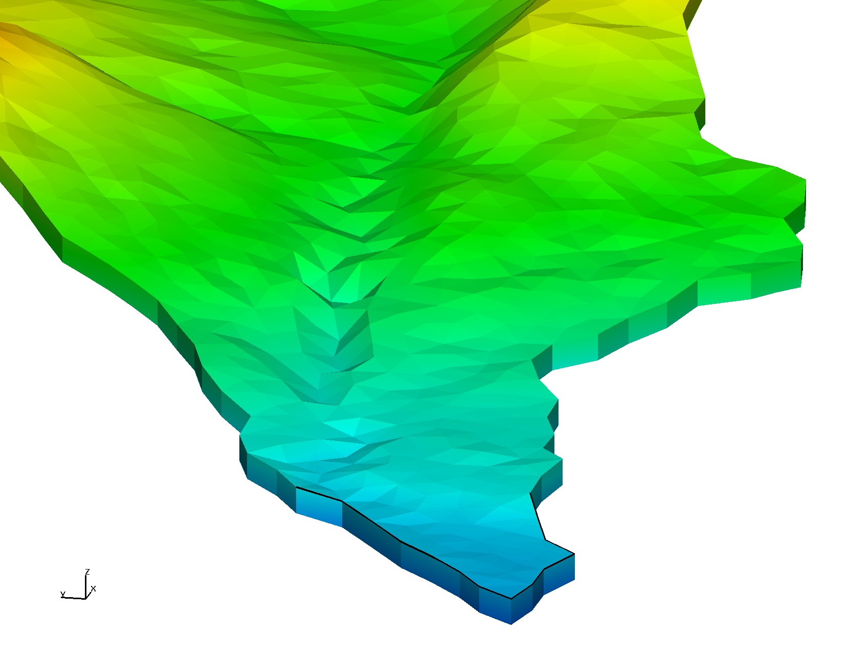
|
sm_fs_outlet_detail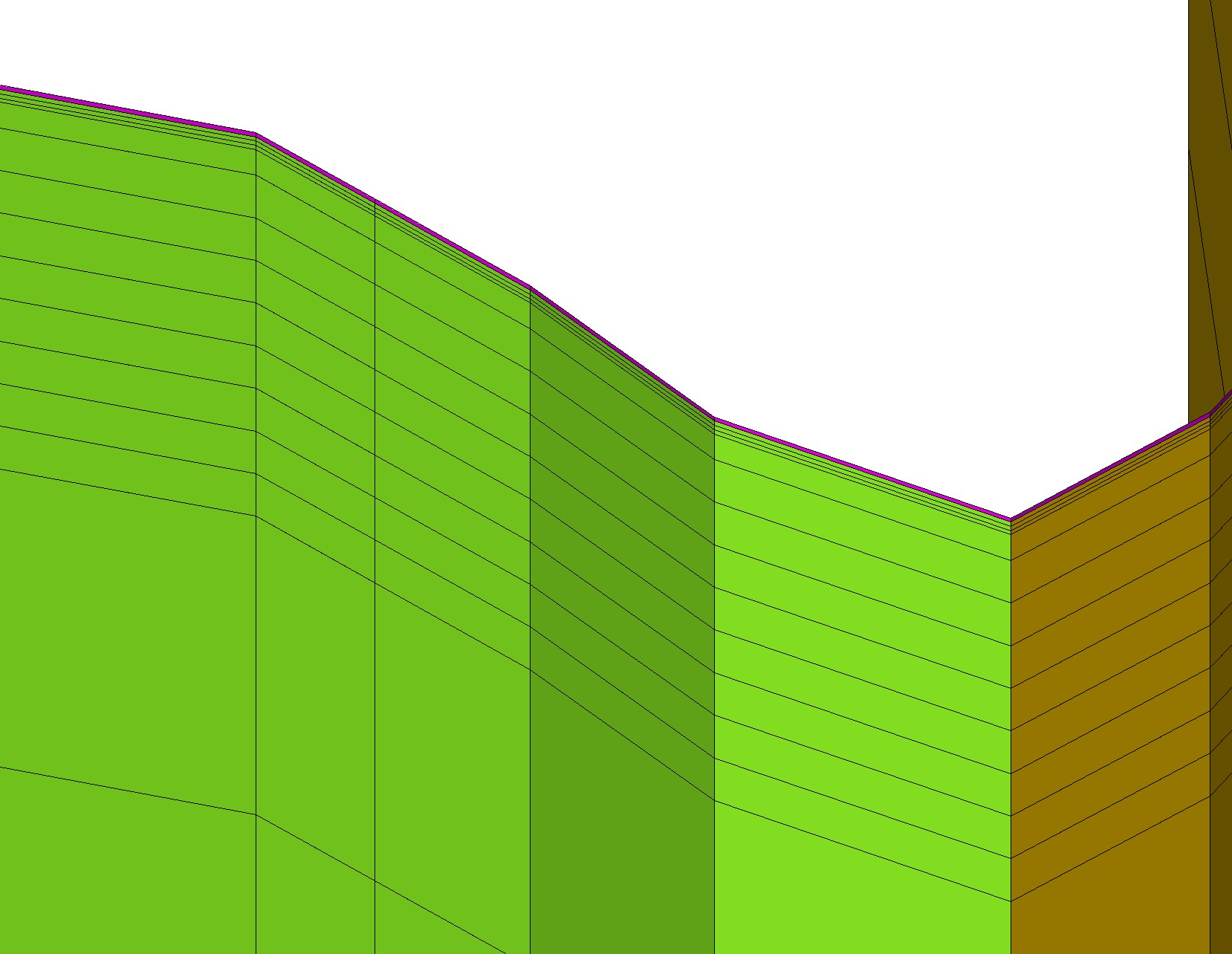
|
sm_fs_outlets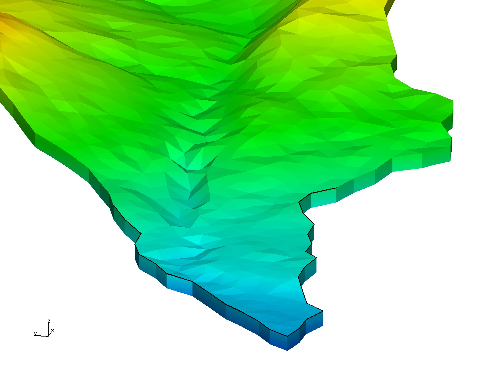
|
uni_mesh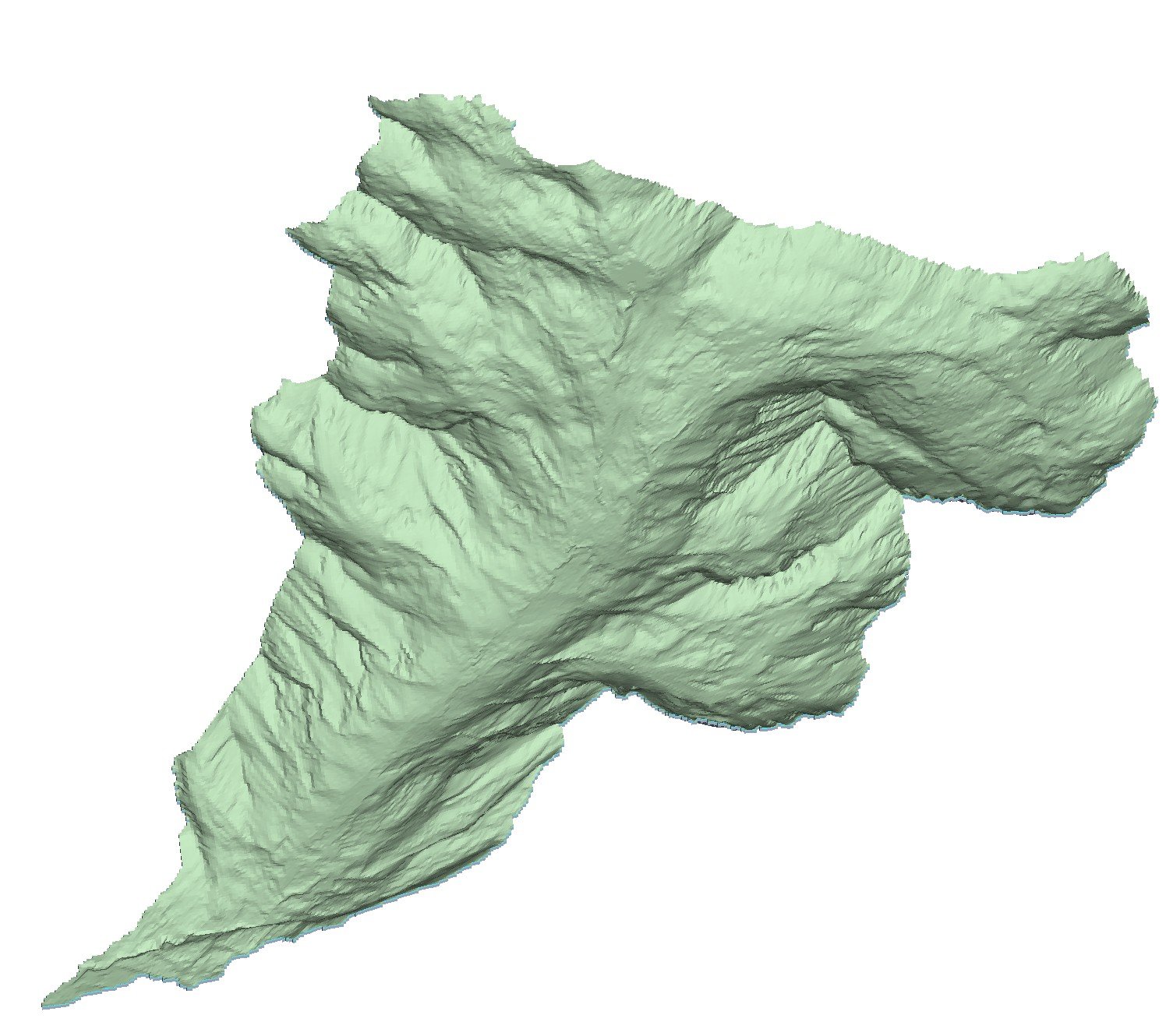
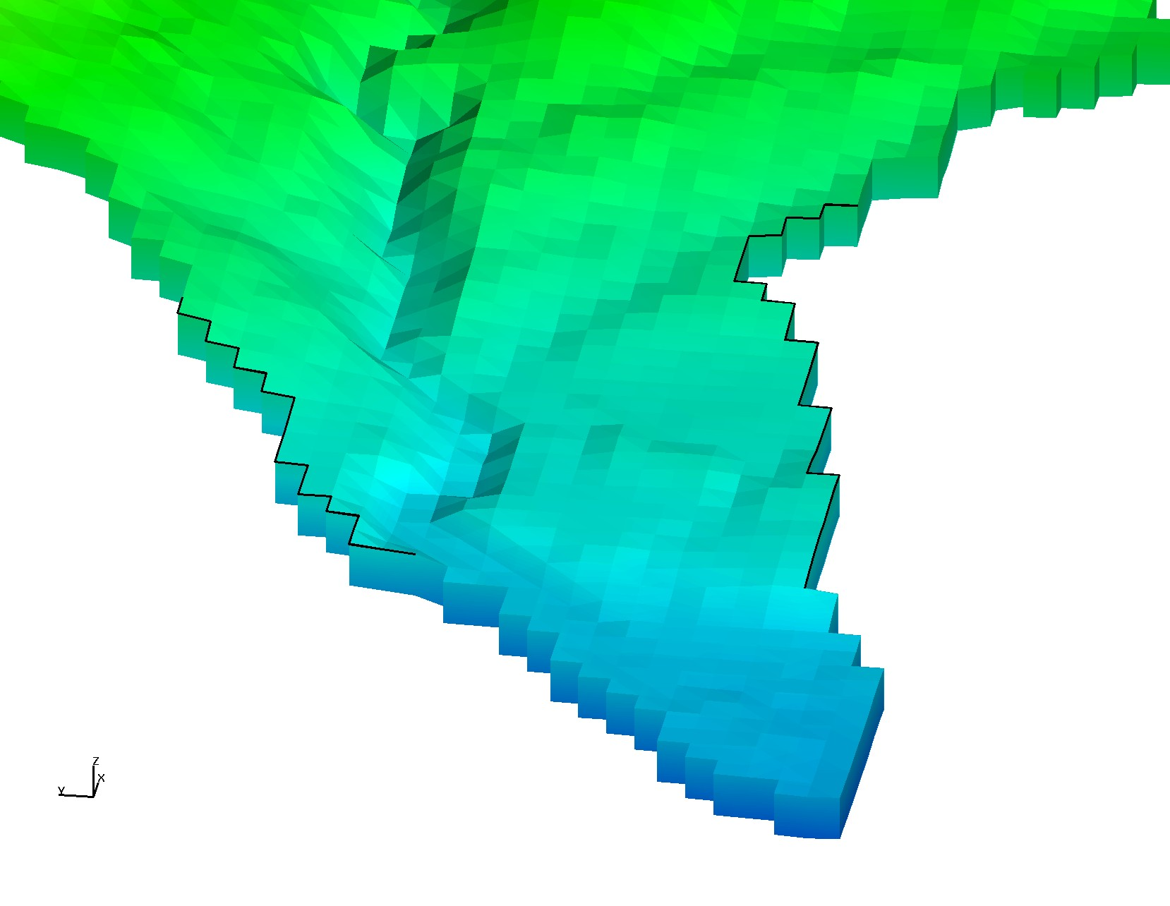
|
uni_facesets_tip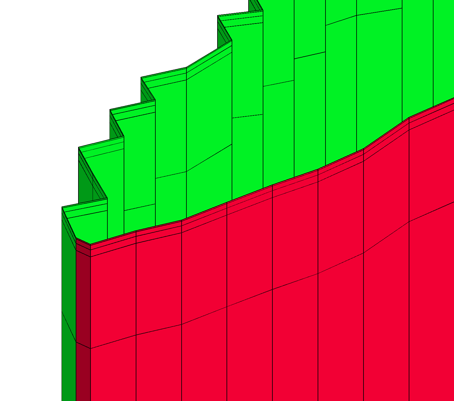
|
uni_fs_outlets
|
Use LaGriT to Write Exodus Mesh file with boundary faces (side sets).
Sets include faces on bottom=1, and top=2)
Sides are defined as 3 (default)
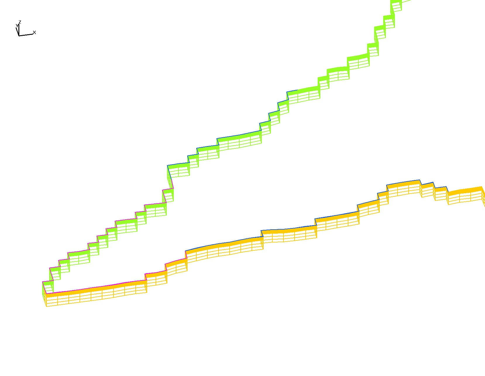
For 7 sets: left=5 and right=3 of center line, and north of back line=4,
and river faces at outlet and layer 1 tip=7, and extended=6
Examples of other methods to select faces for sets
include intesection and bounding box
these were not used in these grids.
xfacesets_river_box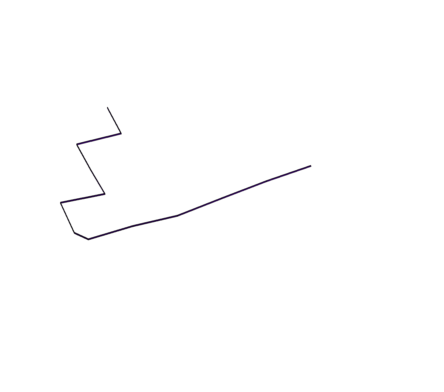
|
xfacesets_river_xsect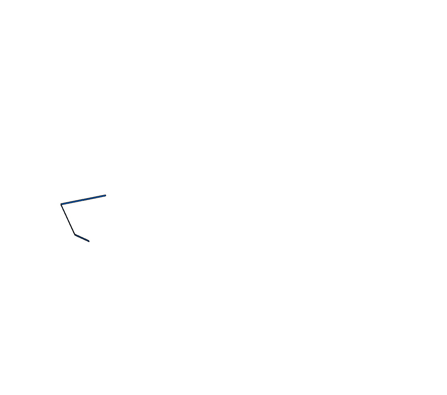
|
xriver_box_select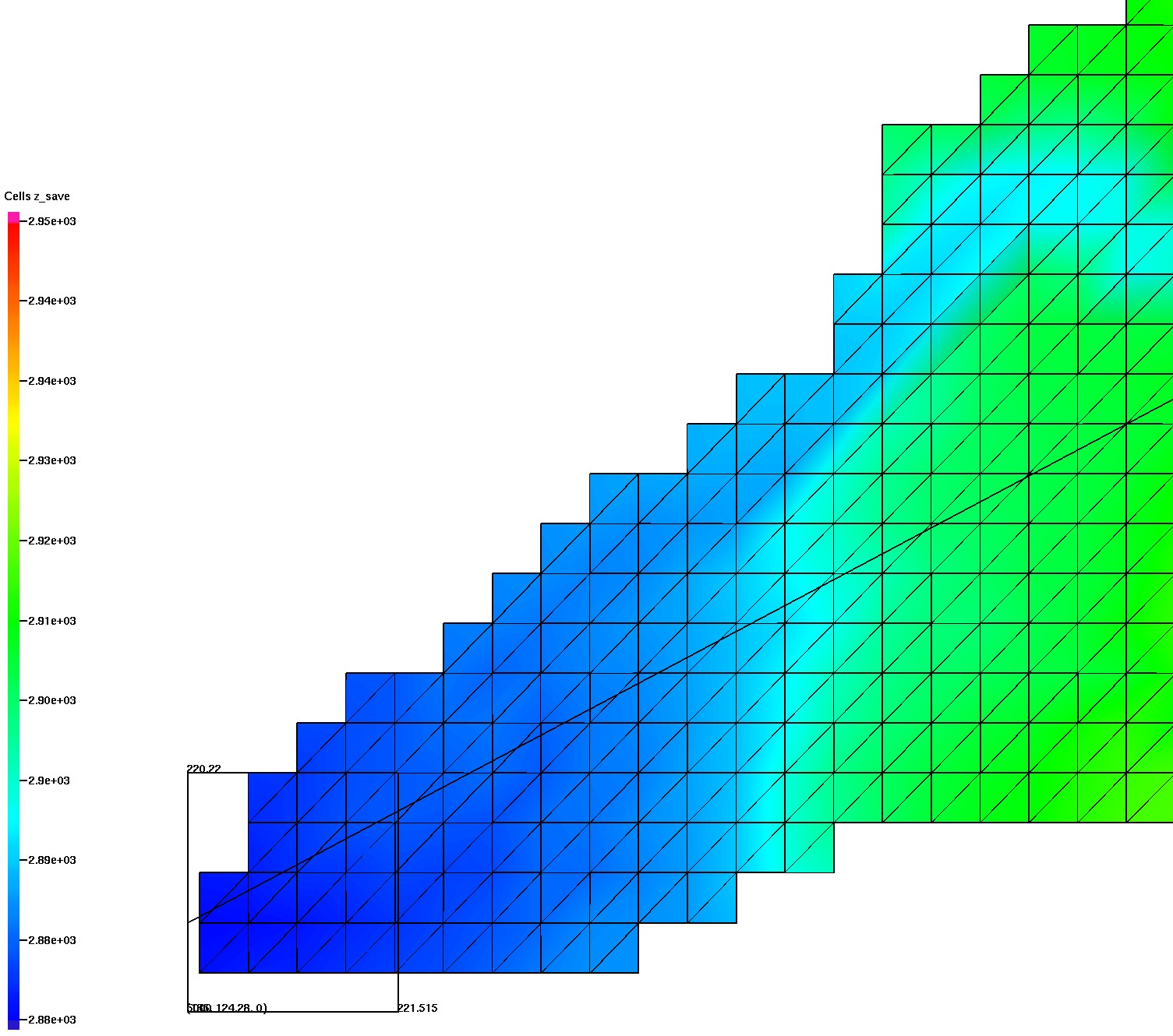
|
uni_line_intersect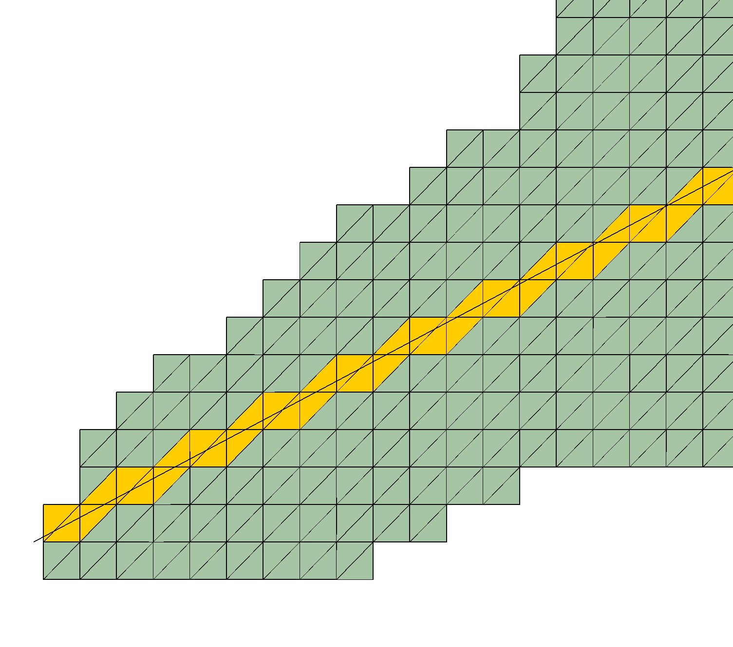
|