Grid Project: Mesh to Point Interpolation
| Grid Team Member: |
Carl Gable |
| Delivered To: |
SCEC Community |
| Date Completed: |
July 2006 |
Purpose:
Create a generic LaGriT control file to automate interpolation of node based
floating point attributes from a finite element mesh onto a uniform distribution
of points. The point distribution can be either a single point, a line of
points, a plane of points orthoganal to coordinate axis or a three dimensional,
orthoganal distribution of points.
Use of the LaGriT control files:
There are four LaGriT control files,
two do the actual work and two are included so that a simple synthetic calculation
can be run to demonstrate the method. The LaGriT control files are:
interpolate_mesh_to_points.lgi
user_control_variables.lgi
example_driver.lgi
create_src_mesh.lgi
All the files (*.lgi *gmv *inp) are in a single archive file:
all_files.tar.gz
To run the example problem:
To run the example problem one would run the LaGriT exacutable (xlagrit):
xlagrit < example_driver.lgi
or after starting up LaGriT from the command prompt:
Enter a command
input example_driver.lgi
Running the example will produce the following output:
input.inp - this is a 3D tetrahedral mesh
created and output by example_driver.lgi. This has some synthetic attributes
set to the nodes. The synthetic node attributes are: e**x, y**2 and sin(z).
These are the values that will be intrerpolated from (source mesh) and assigned
to the sink mesh nodes. In an actual application, this is the file that would
be provided by the user.
output.gmv - This is a node distribution
(161x41x1 for the example) with the interpolated values. The file is GMV
format.
output.inp - This is a node distribution
(161x41x1 for the example) with the interpolated values. The file is AVS
format.
output.table - This is a node distribution
(161x41x1 for the example) with the interpolated values in a tabular format.
unit_cube_tet_11_11_11.gmv
- This is a GMV format file of the input source mesh.
unit_cube_tet_11_11_11.inp
- This is an AVS format file of the input source mesh. It is the exact same
file as input.inp.
To run an actual problem:
It is expected that you have an AVS format file (output from Pylith, etc.)
that is the result of a model run and you wish to interpolate the output
onto a different point distribution.
Step 1) Edit the file user_control_variables.lgi
*
* Define input and output file names.
*
define / INPUT_AVS / input.inp
define / OUTPUT_AVS / output.inp
define / OUTPUT_GMV / output.gmv
define / OUTPUT_TAB / output.table
*
* Define the extents in the x y and z directions.
* Set min = max and N*_POINTS = 1 for a plane of points.
*
define / XMIN_PTS / 0.1
define / YMIN_PTS / 0.1
define / ZMIN_PTS / 0.5
define / XMAX_PTS / 0.9
define / YMAX_PTS / 0.9
define / ZMAX_PTS / 0.5
*
* Set the number of points to be created in the x y and z directions.
* Set all three to numbers greater than 1 to create a cube of points.
* Use 1 for a single direction to create a plane of points.
* Use 1 for two directions to create a line of points.
*
* For this example that goes from x = 0.1 - 0.9
* distribute 161 x points so that dx = 0.005
* distribute  41 y points so that dy = 0.020
*
define / NX_POINTS /  161
define / NY_POINTS /  41
define / NZ_POINTS /  1
*
* Define the name of three the attributes to be interpolated.
* Since this is written assuming an AVS format file is being
* read as input, it is assumed that the attribute names will
* be contained in the INPUT_AVS file. The number of attributes is
* hardwired to three. If you wish to have fewer or more attributes
* interpolated it will require editing of the control file:
*  interpolate_mesh_to_points.lgi
*
define / ATTRIBUTE1 / xdisplace
define / ATTRIBUTE2 / ydisplace
define / ATTRIBUTE3 / zdisplace
*
* This is the value that an attribute will be set to if it is
* outside the source mesh.
*
define / IF_OUTSIDE_FLAG / -9999.9
Step 2) Run the LaGriT exacutable (xlagrit):
xlagrit < interpolate_mesh_to_points.lgi
What does this do?
Most of the control file is doing book keeping, setting up the mesh objects,
controling output, etc. The guts of the calculation is in the 'interpolate'
commands:
interpolate / continuous / cmo_sink / ATTRIBUTE1 / 1 0 0 / &
                           cmo_src  / ATTRIBUTE1 / IF_OUTSIDE_FLAG keepatt
interpolate / continuous / cmo_sink / ATTRIBUTE2 / 1 0 0 / &
                           cmo_src  / ATTRIBUTE2 / IF_OUTSIDE_FLAG keepatt
interpolate / continuous / cmo_sink / ATTRIBUTE3 / 1 0 0 / &
                           cmo_src  / ATTRIBUTE3 IF_OUTSIDE_FLAG
For a description of the syntax see the LaGriT manual page: interpolate
The basic algorithm is to use a kd-tree search to locate the element of the
sink mesh (cmo_sink) that each node of the source mesh (cmo_src) is located
in. Then use linear interpolation to interpolate the floating point node
values from cmo_src, ATTRIBUTE1 onto the floating point node values of cmo_sink,
ATTRIBUTE1.
|
|
|
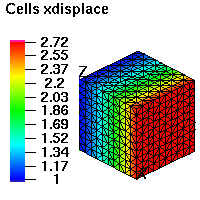
Source mesh from example showing xdisplace=e**x values.
|
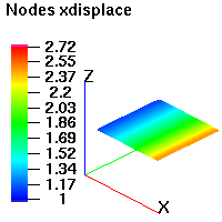
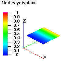
Sink nodes from example showing interpolated values
of xdisplace. Individual nodes are not visable because the high node density
appears as continuous.
|
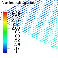
Close up of nodes showing the individual nodes.
|
|
|
|
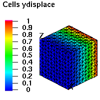
Source mesh from example showing ydisplace=y**2 values.
|
Sink nodes from example showing interpolated values
of ydisplace. Individual nodes are not visable because the high node density
appears as continuous.
|
|
|
|
|
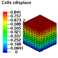
Source mesh from example showing zdisplace=sin(z)
values.
|
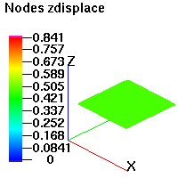
Sink nodes from example showing interpolated values
of zdisplace. Individual nodes are not visable because the high node density
appears as continuous.
|
|
Project Archive Location
/scratch/ymp/gable/grid_gen/crustal_deformation/bm_grid_to_node_interpolation
Grid Team Contacts
| Carl Gable |
gable -at- lanl -dot- gov |
505-665-3533 |
| Terry Miller |
tamiller -at- lanl -dot- gov |
505-667-8009 |