The grid generation strategy is to create a grid to represent
an SK Tank and surrounding materials. A cell dimension of about .5 meters
is needed to resolve the interface between the tank and background materials.
However, to resolve key geologic and hydrologic gradients in the areas
of interest and in an effort to decrease the number of nodes, three zones
of resolution are used. In the lower elevations of the model, defined
up to Hanford Fine Sand at 30 meters, a resolution of about 2 meters is
used. In the middle of the model in the Sand at about 35 meters,
a resolution of 1 meters is used. In the tank and surrounding materials,
a resolution from .2 to .5 meters is used for the finer resolution at the
tank boundary. The steps followed for this method are outlined below.
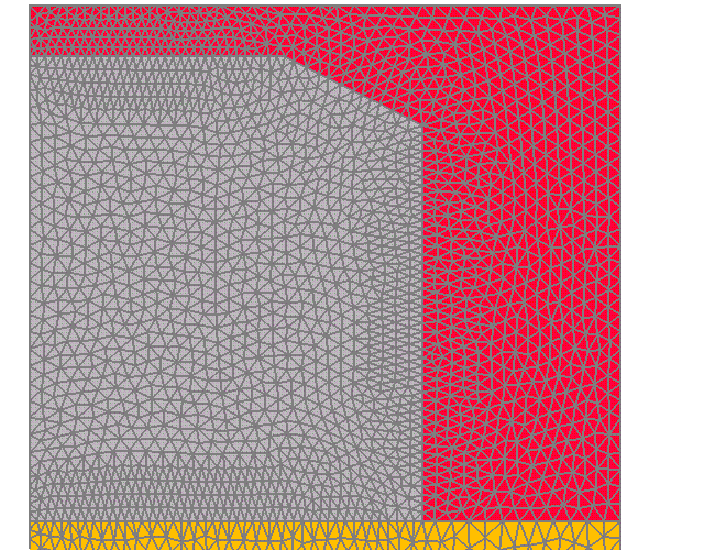
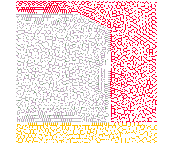
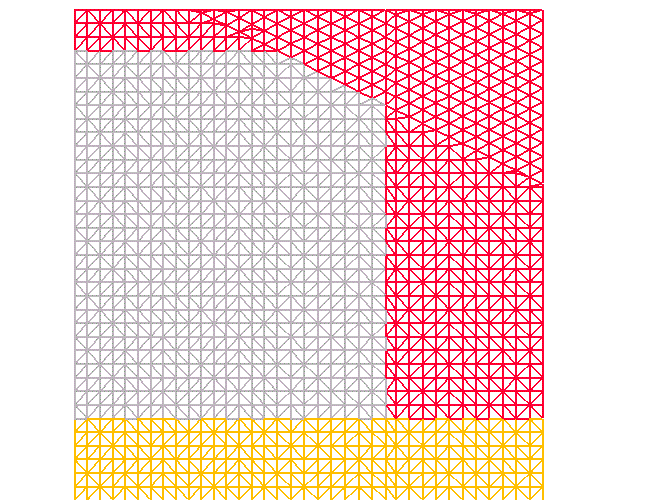
Close-up of top of grid with Tank in gray, backfill in red, and Hanford
Fine Sand in orange. Top image shows the triangulation and below are the
voronoi areas.

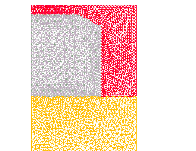
Top of grid on the left, the remainder of the grid on the right. Materials
from bottom to top are; saturated (dark blue), Upper Ringold (light blue),
Plio-Pleistocene (dark green), Hanford Fine Sand (yellow green), Backfill
(red) and Tank (gray). Smallest edge lengths occur at the tank boundary
at about .2 meters. The bottom of the grid has the longest edge lengths
at about 2 meters.
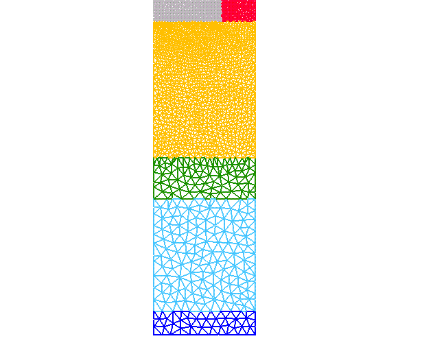
Meters Surface-Name
68. Top
66.5 Tank
68. Backfill
53. Hanford Fine Sand
30. Plio-Pleistocene
23. Upper Ringold
4. Saturated
0. Bottom
Start with a line of points located above the grid that are used for ray shooting for generating points. These points are .5 meters apart, with a closer distribution where the rays will shoot through the slanted part of the tank. Points are created every .5 meters along the y direction. The generated points are connected into a triangulated grid.
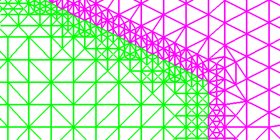
Use refine/rivara to divide triangles around the tank boundary. Along
the slanted portion of the tank, refinement needs to be extended to avoid
gaps occurring at the tank corners. Massage is used to remove skinny triangles
and fanning along the tank edges. Massage is also used to derefine the
grid starting in the sand and to the bottom of the grid. Smoothing is used
to improve the point distribution and help achieve a computable grid.
Refinement at tank boundary.
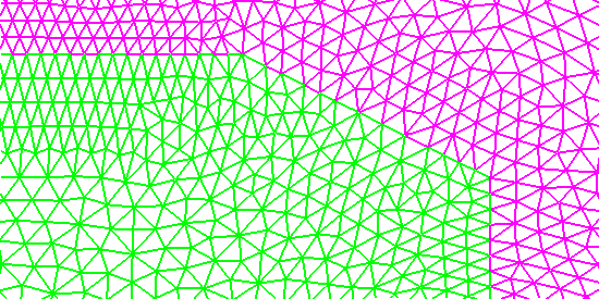
Massage improves tank boundary by removing skinny triangles and fanning.
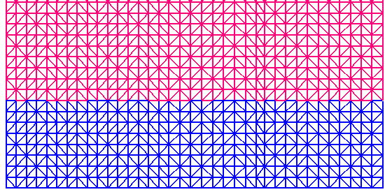
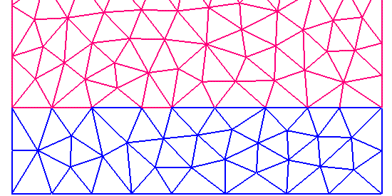
Top image shows the grid bottom before derefinement. The next image
shows same grid after increasing edge lengths from .5 meters to 2. meters.
From the reconnected Delaunay grid, files for FEHMN are written. This is done first with the tank included as a material, then with the tank removed.
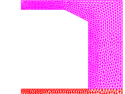
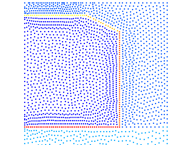
The points along the boundary of the tank are identified in files bndry_tank.pts and bndry_rmtank.pts. Below the grid points are colored by their location on the tank boundary. Yellow points are at the top of the tank (front_s), yellow green points are the slanted top (front_s), orange points are the tank side adjacent the backfill (left_w), red points are the bottom of the tank (back_n).
