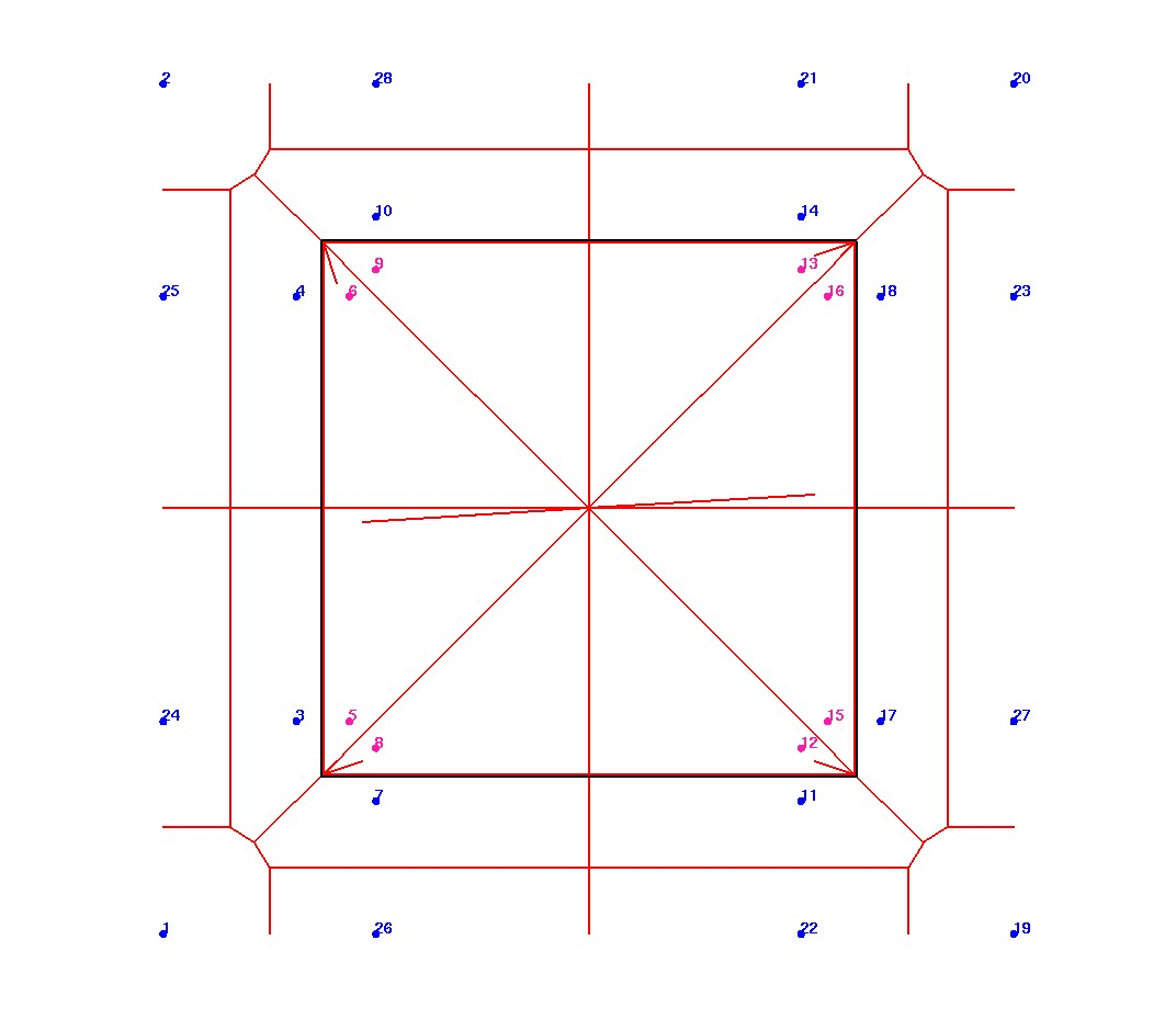
Connected Tets (blue and red)
Surface constraining seeds (blue)
Considerations for a GFM to Voronoi generator to Modeling:
What are constraints on input?
i. single material: piecewise linear complex (triangle) bounding airtight volumes
ii. multi-material: coincident piecewise linear complexes (triangle) bounding multiple airtight volumes
What type of output are possible?
Material properties
Boundary conditions
Variable resolution,
High aspect ratio geometry, anisotropic meshing,
Non-manifold geometries
Visualization of results?
Output Voronoi polygons, Generator seeds, Paraview (or other?)
Directory: /project/ep_cr/tam/meshing/Examples/proto_vor_tet/
Input Surface
|
|||
|
VoroCrust Cells (wire) and Connected Tets (blue and red) |
Interior seeds (red) Surface constraining seeds (blue) |
VoroCrust Voronoi Polygons |
VoroCrust Voronoi Polygons Clipped |
Images show VoroCrust meshing results.
Input is a triangulated surface representing the volume to fill.
VC will generate seed points (voronoi centers). These are interior (with voronoi cells full inside)
and surface constraining (inside and outside the surface).
The result is a volume filled with voronoi polygons with variable number of faces.
VC creates many surface seeds which may be difficult to view and evaluate.
Note, Input models assume vornoi cells around each node point formed from tetrahedral.
Directory: /project/ep_cr/tam/meshing/Examples/simple_tests/flat_1bndry
Input Surface with 2 Materials
|
vc_surface
|
vc_surface_with_opacity
|
Directory: /project/ep_cr/tam/meshing/Examples/simple_tests/2D_1mat_wave
Input Surface
|
|||
SP2D_1mat_quin_h20_wave175
|
SP2D_1mat_quin_h30_wave175
|
SP2D_1mat_rand_h20_wave175
|
SP2D_1mat_reg_h20_wave175
|
To better understand VC output we create a simplified 2D cube with possible seed locations.
Each corner has 4 seeds located inside and outside of the boundary surface.
The seed points into a Delaunay mesh and Voronoi volumes and areas are computed using LaGriT.

Page for PROTO1 2D Box