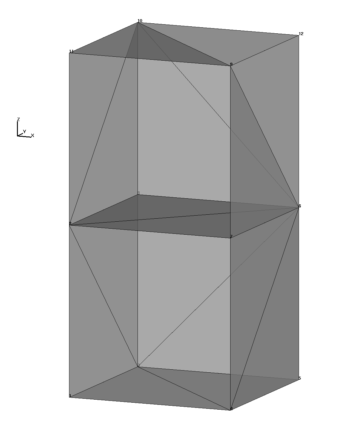
Input Surface
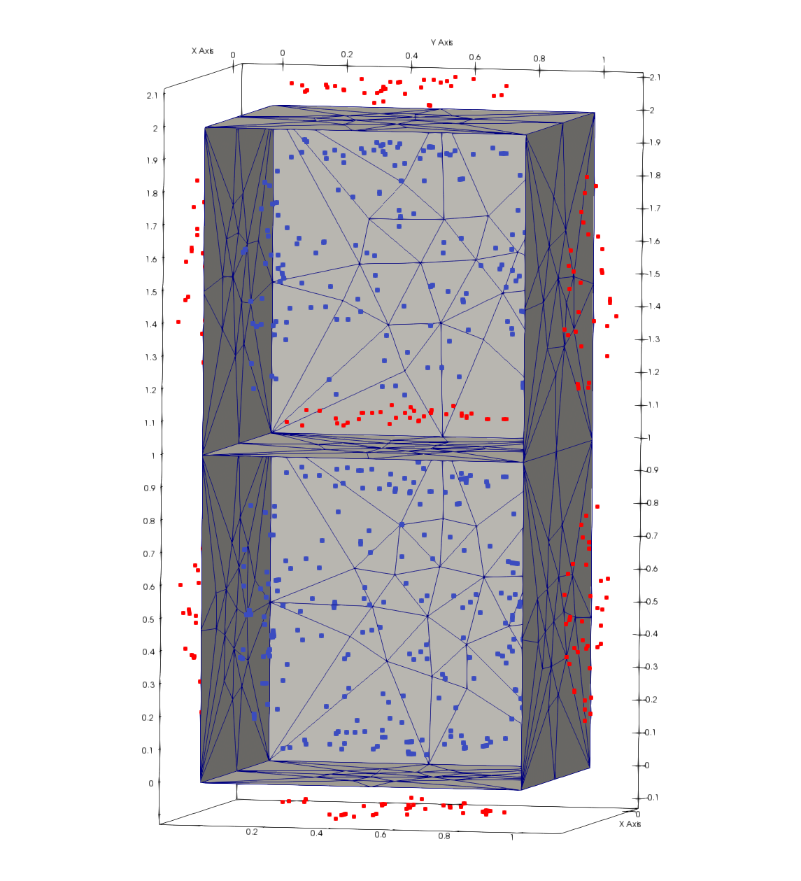
VoroCrust Exterior and Interior seeds
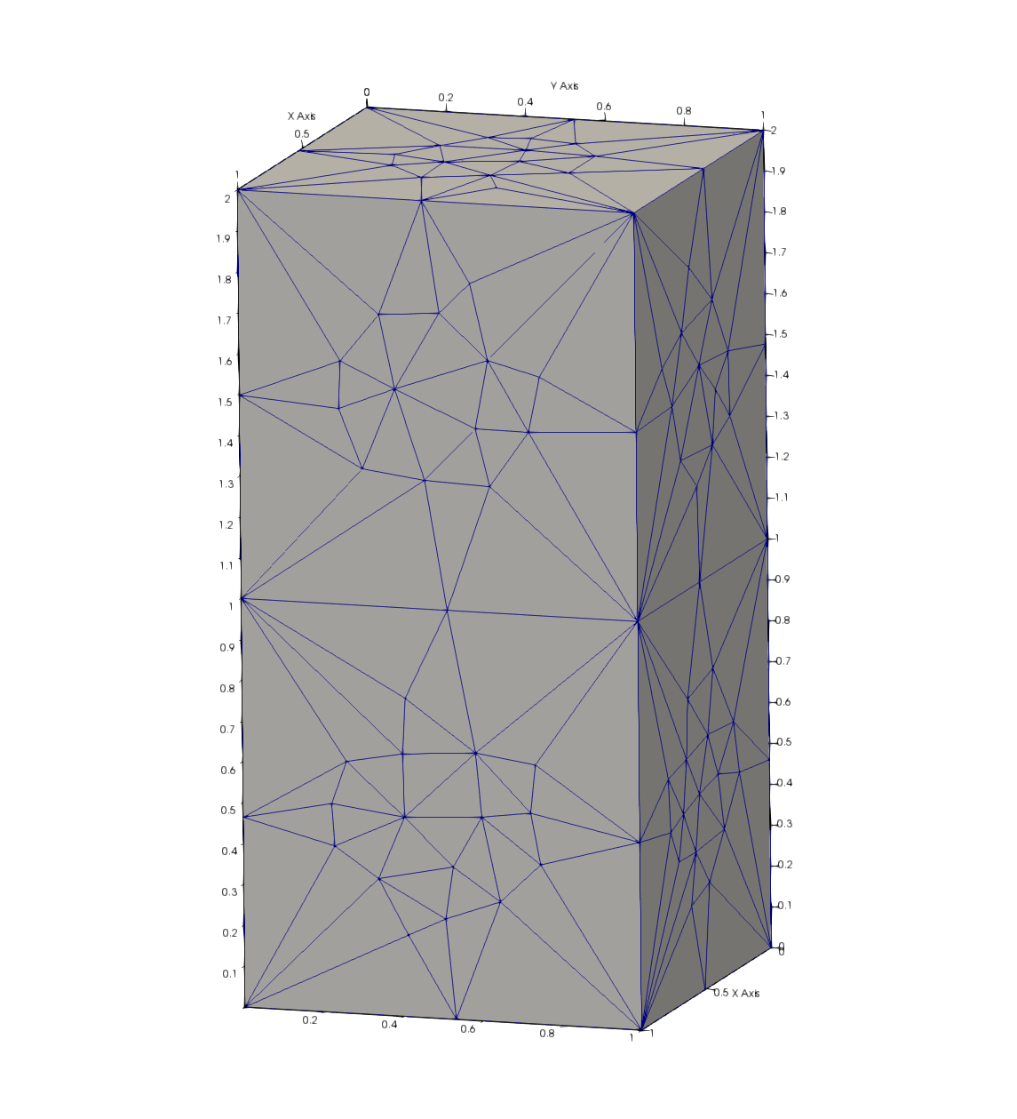
VoroCrust Surface Mesh
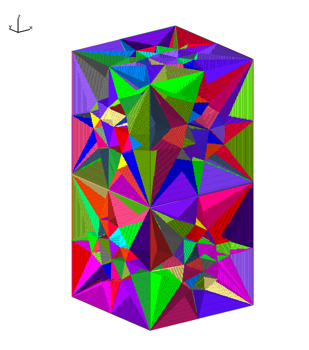
Voronoi Cells Interpolated from seeds
| Mesh Team Members: | Terry Miller, Carl Gable, Daniel Livingston |
| Modeling Team Members: | Phil Stauffer |
| VoroCrust (SCR-2020.1): | Government Use of VoroCrust to LANL (#10988) |
| VoroCrust Author: | Mohamed Salah Ebeida (SNL) |
| Work in Progress: | June 7 2019 |
| Collaborations With: | SNL Tara LaForce and Emily Stein |
| SFWD Projects Main Page: | SFWD Geo Integration |
| Local Working Directory: | /project/meshing/GEO_Integration/work |
Geometry conforming Voronoi tessellations for geologic flow and transport calculations are the goal of this project. These will be used in flow and transport codes FEHM and PFLOTRAN but will also be applicable to modeling with Amanzi and Tough2.
This work is supported by Spent Fuel and Waste Disposition (SFWD) programs within the Spent Fuel and Waste Science and Technology (SFWST) Campaign of the U.S. Department of Energy (DOE) Office of Nuclear Energy (NE). The program is tasked with conducting research and development (R&D) related to geological disposal systems.
This year SNL will work with VoroCrust to develop Voronoi geometric coefficients for PFLOTRAN for use in idealized sample models. LANL is continuing work with VoroCrust to develop a meshing workflow for FEHM, PFLOTRAN and geologic models in general.
VoroCrust Abstract arxiv.org/abs/1902.08767
VoroCrust: Voronoi Meshing Without Clipping PDF
VoroCrust Supplemental Materials
PDF
The following are example geologic geometries used with VoroCrust to explore meshing parameters and results. These include both manifold and non-manifold geometries with internal boundaries. The files are available on github LANL (Private).
This is multi-material with one internal boundary, 2 unit cubes.
This allows for easy testing of volumes, parameter options, and VIS methods.
This example includes a buffer to protect corners (not needed), and a no buffer versions.
VoroCrust generates seeds away from the boundary and far enough to capture the corners.
Developed method to VIS Voronoi cells from vorocrust seeds using LaGriT interpolation method.
Includes Delaunay Tet mesh files for FEHM modeling

Gallery of Unit Cubes Work Gallery
|
Input Surface
|
VoroCrust Exterior and Interior seeds
|
VoroCrust Surface Mesh
|
Voronoi Cells Interpolated from seeds
|
Surface with Mortandad Mesa DEM and no internal boundaries, thick and thin versions of depth from top.
Includes of VIS Voronoi cells from vorocrust seeds using LaGriT interpolation method.
Thin layer version tested with flat bottom 10m from lowest top elevation
Gallery of Mesa Shell Mesa Gallery

Gallery of Mesa Thin Layer Thin Mesa Gallery

Mortandad Seismic Project Page Grid Project Page
|
Input Surface 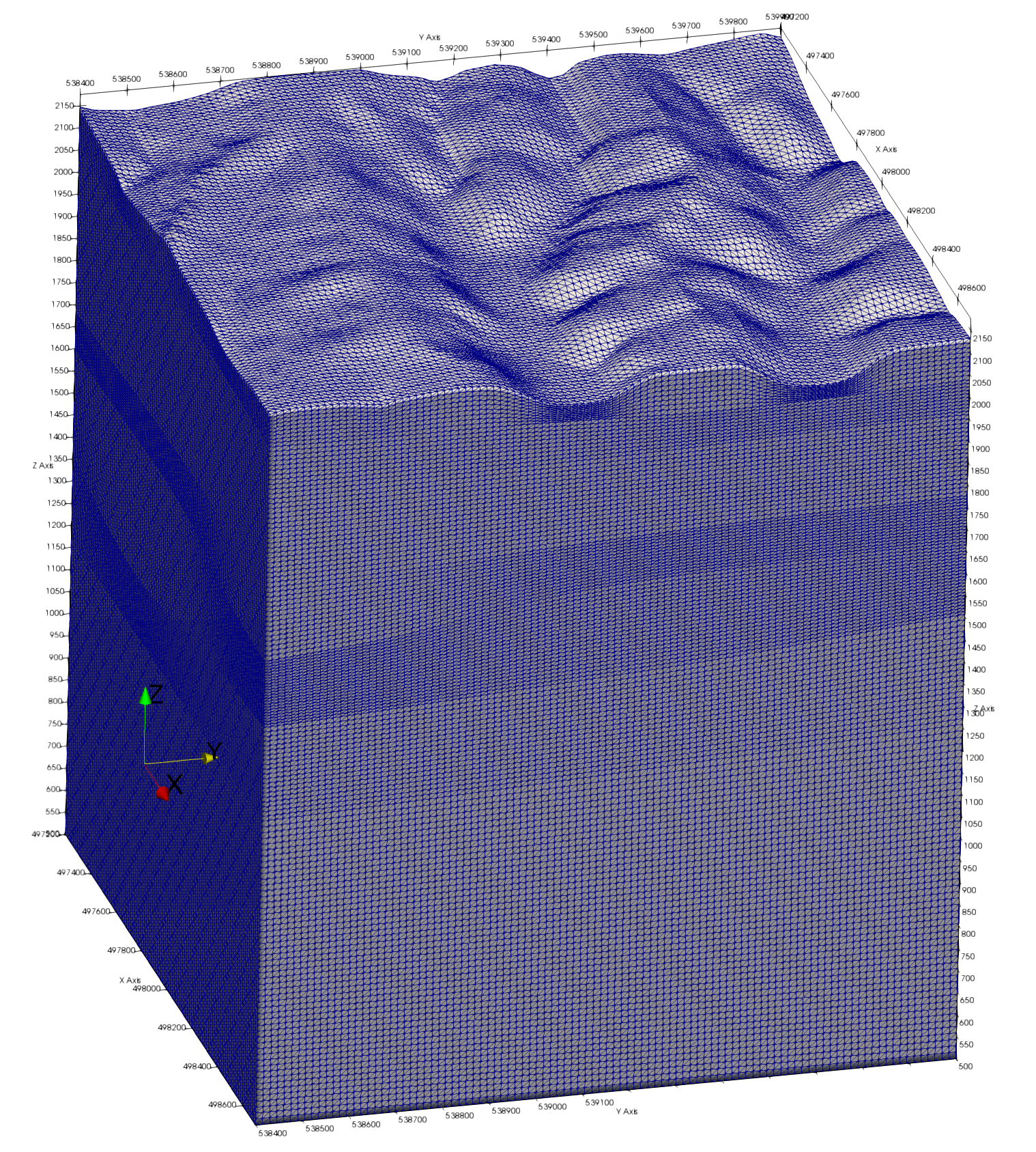
|
VoroCrust Surface Mesh 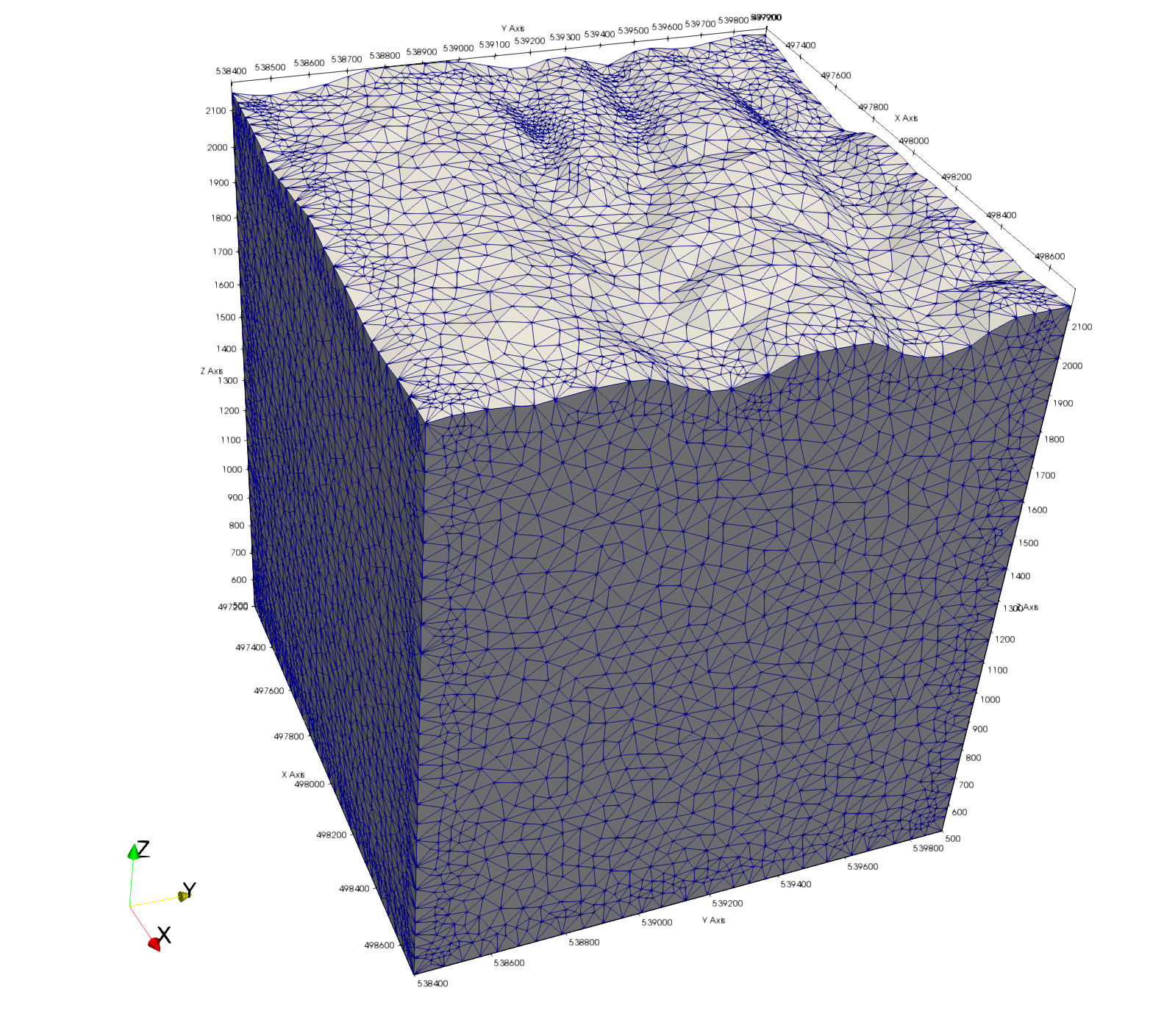
|
VoroCrust Surface Mesh of Thin Layer 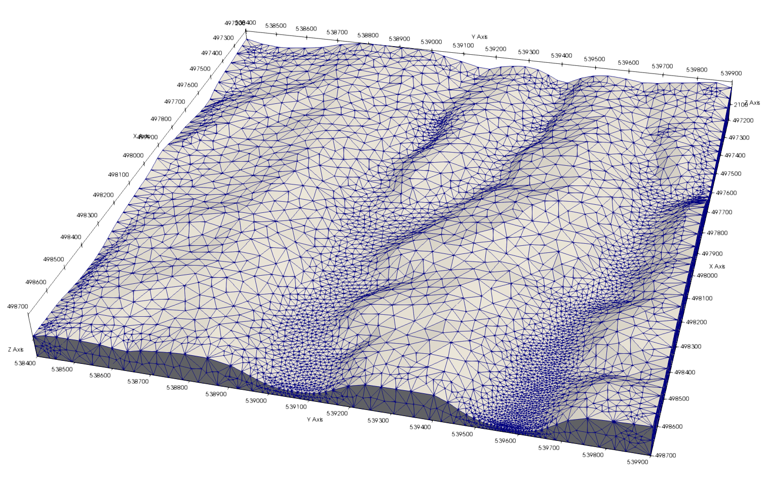
|
Detail of VoroCrust Thin Layer 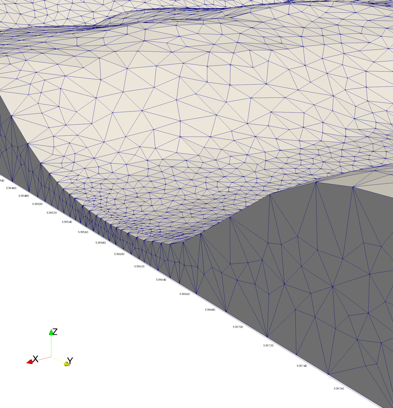
|
|
Voronoi Cells shown on corner subset 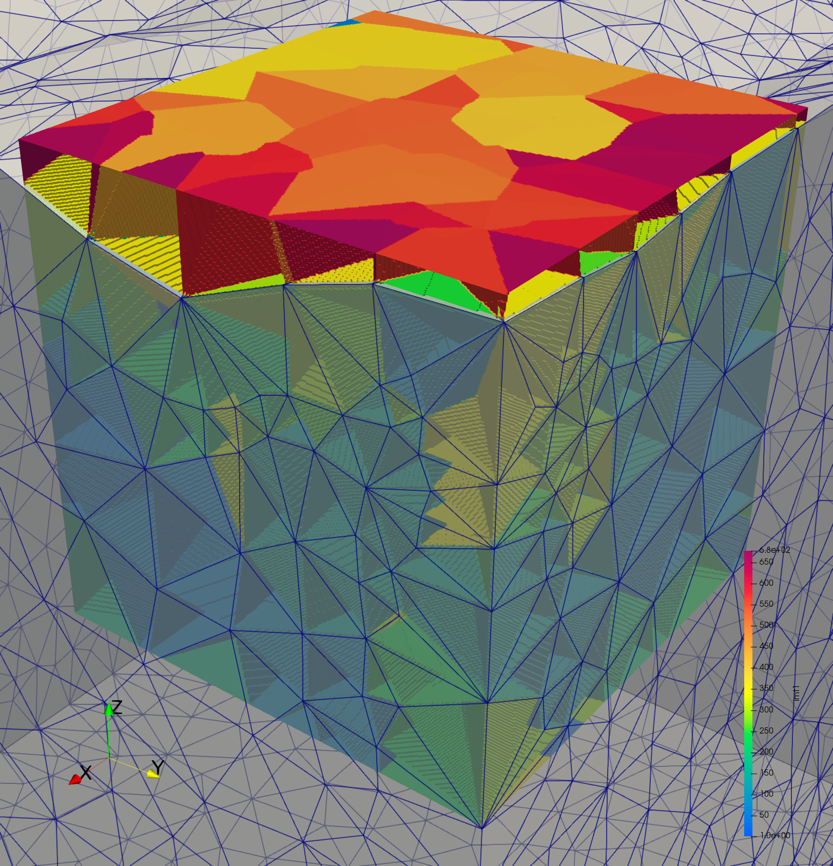
|
Voronoi Cells on Corner Surface 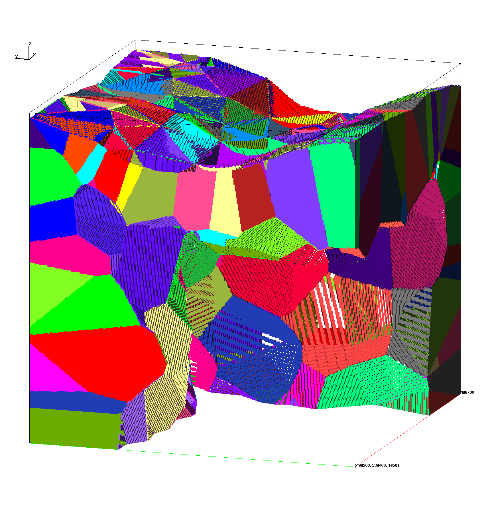
|
Voronoi Cells Corner Interior Volume 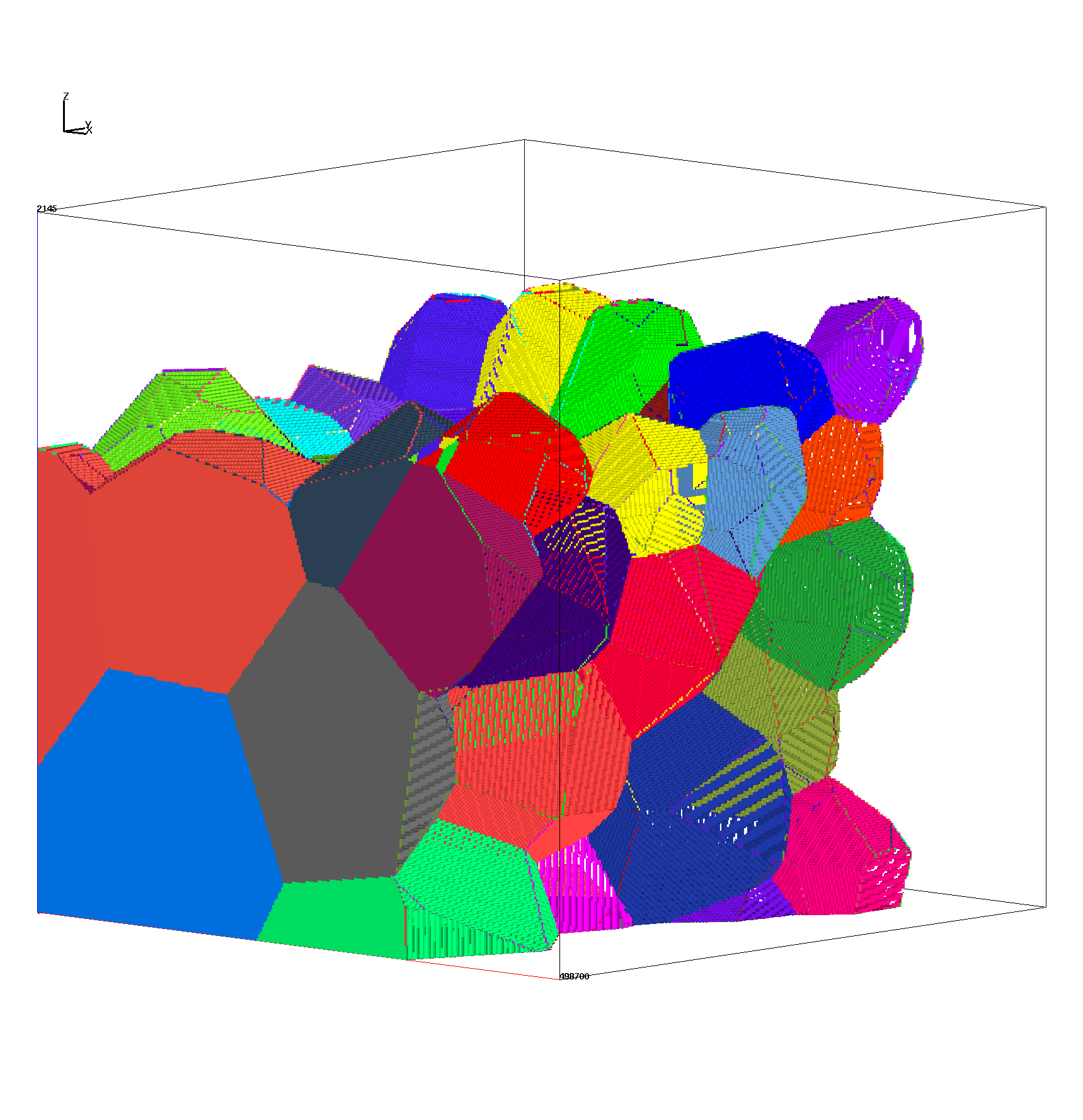
|
Voronoi Cells Inner Volume Thin Mesh 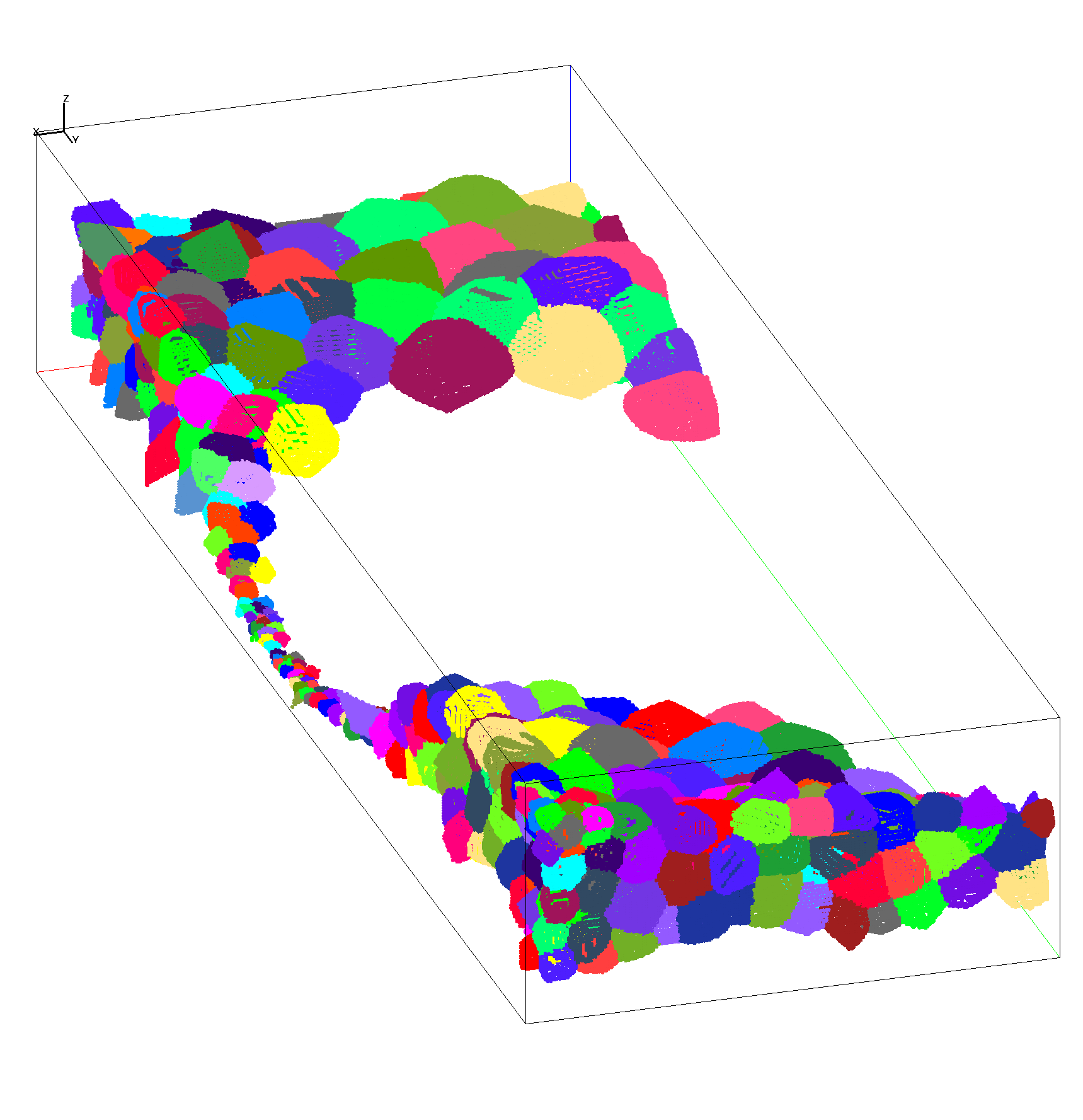
|
These are the 4 Cube Tests from JewelSuite used as test GFM's for the SFWD-GDSA Workflow Integration Project.
These represent test GFM models with 1. horizontal layers, 2. pinchout, 3. lens, and 4. fault.
See the gallery for images of the VoroCrust input surfaces and the VoroCrust Meshing results.
Gallery of VoroCrust Meshing Gallery

Images are clipped from the front to show the internal boundaries.
|
VoroCrust Mesh Test 1 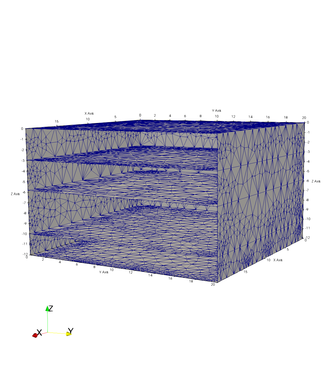
|
VoroCrust Mesh Test 2 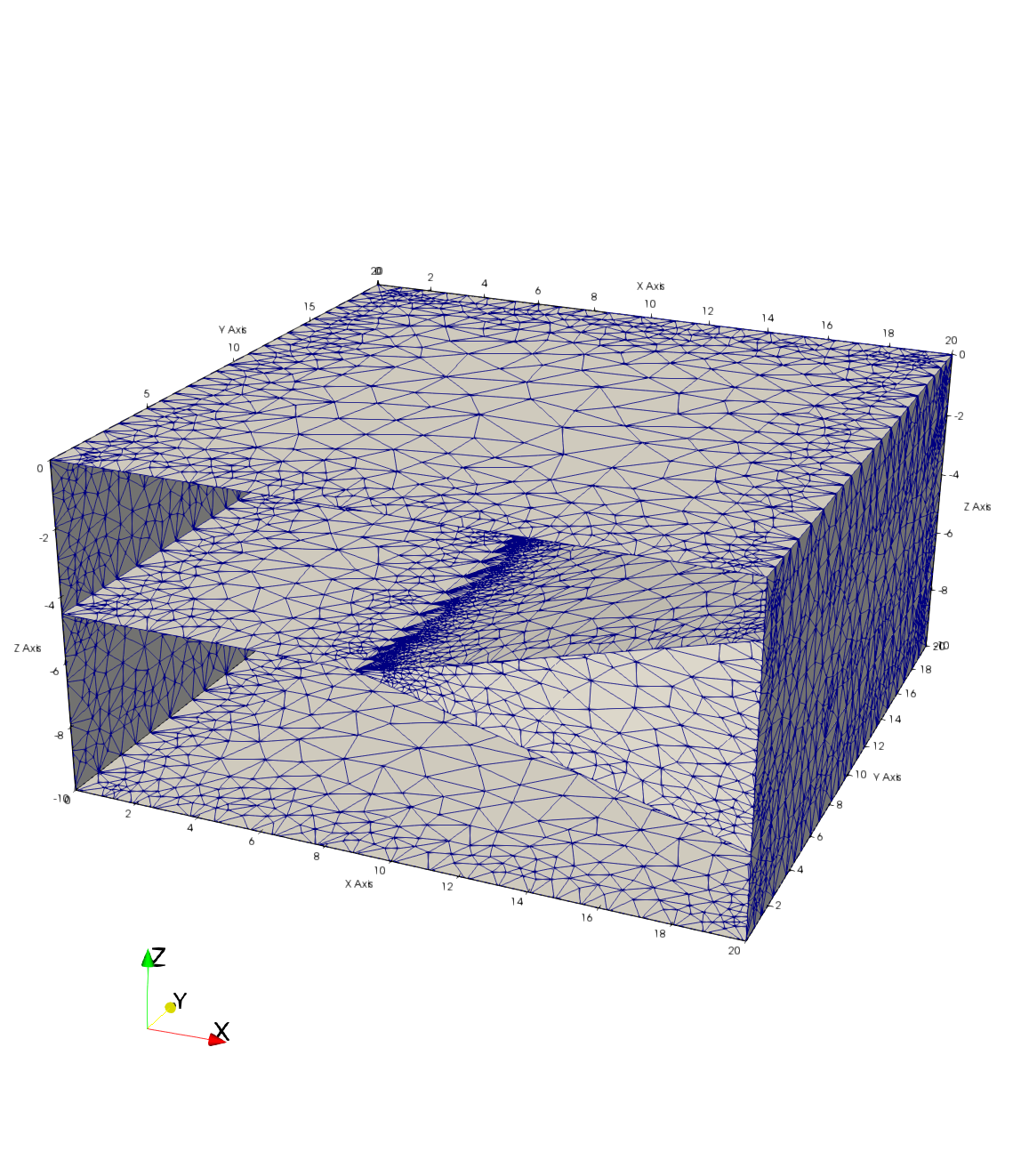
|
VoroCrust Mesh Test 3 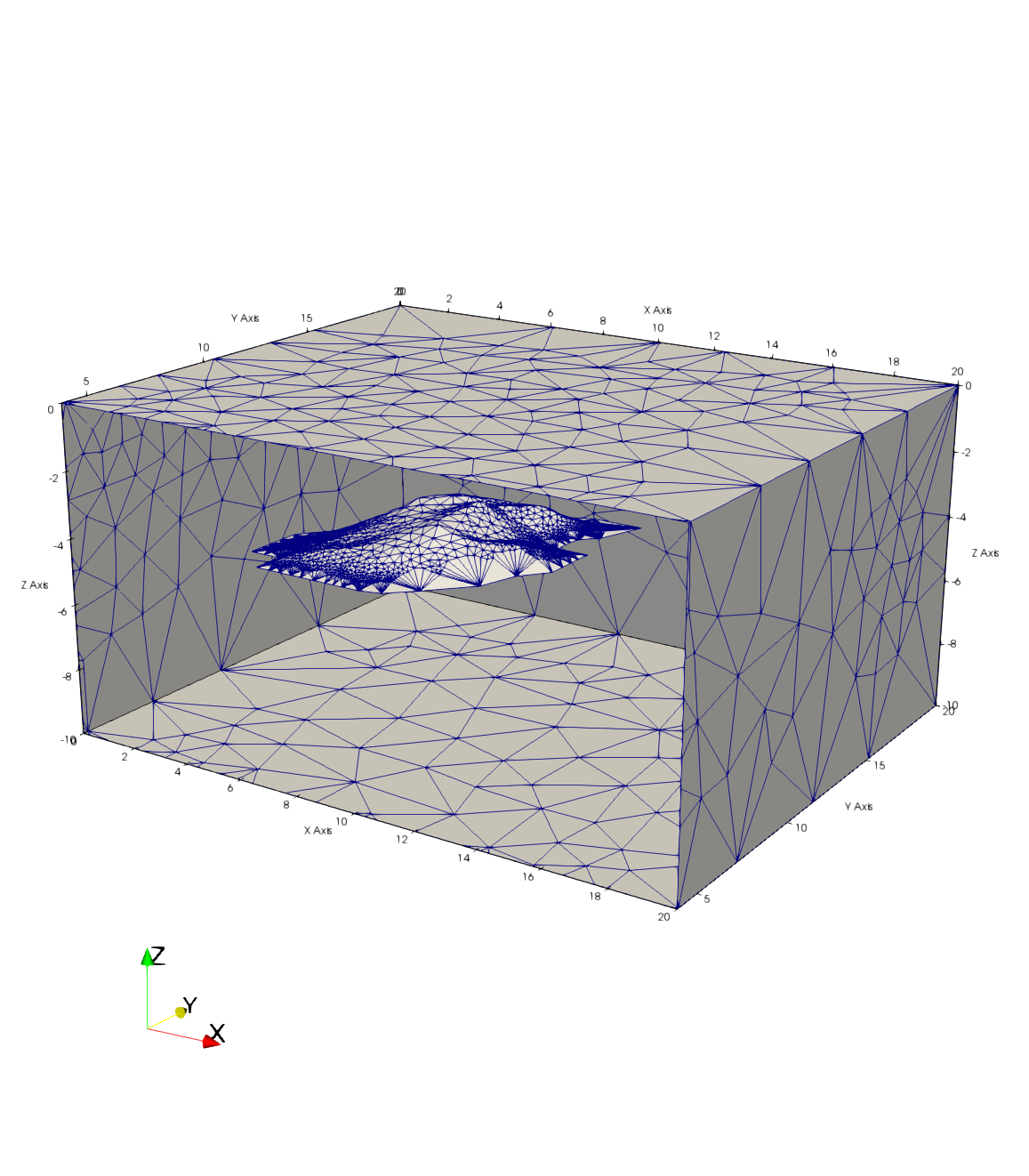
|
VoroCrust Mesh Test 4 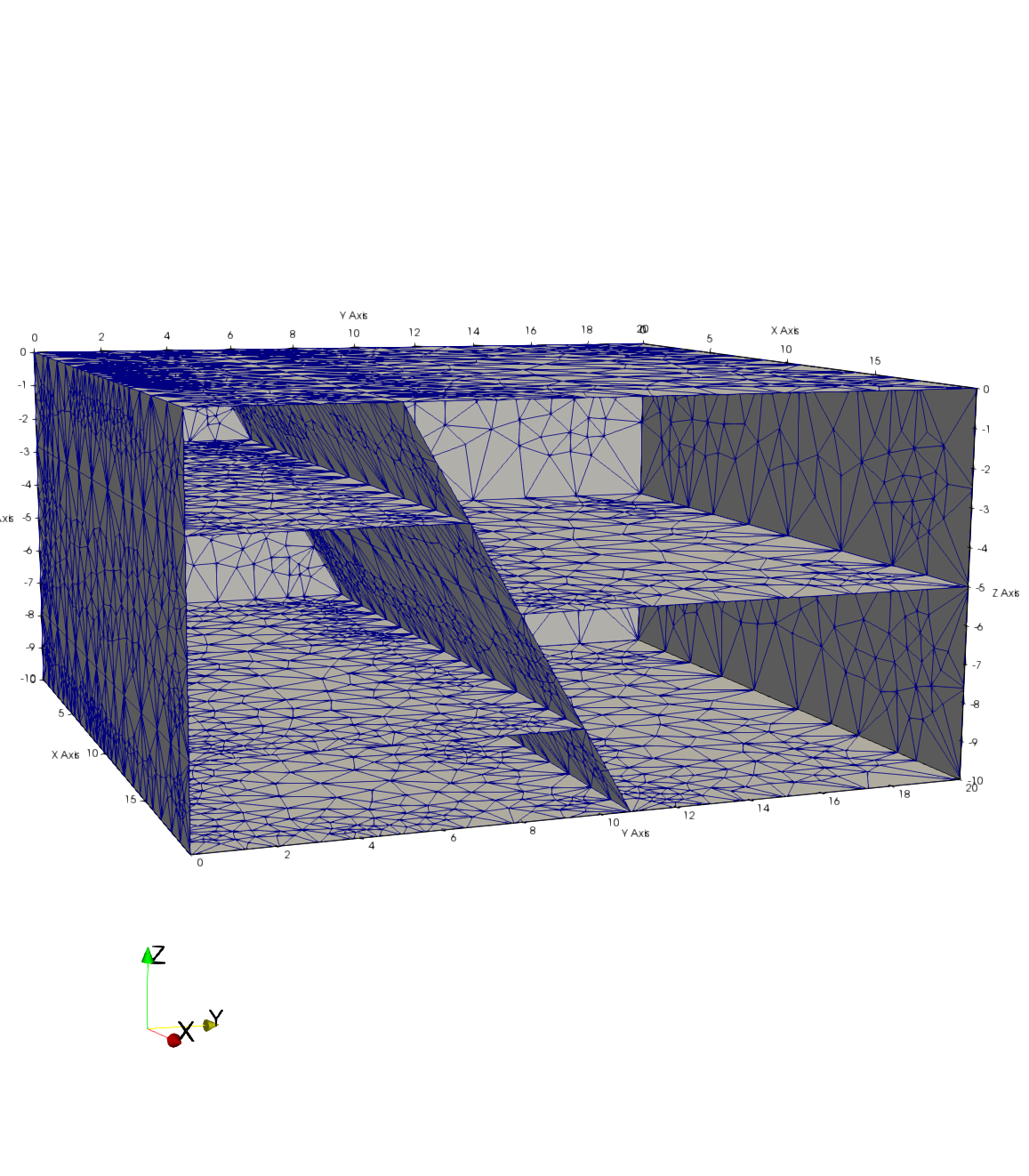
|
These surfaces are from the EarthVision GFM representing the Wyoming Uplift. This model can be difficult for meshing, some of the layers are thin with respect to the region they cover and the slopes of each surface vary subtley with the next layer. Additionally, the slopes of these surfaces range from 6 degrees to over 25 degrees. The challenge is to capture these slopes as well as the thin layers.
The faults were not used in these examples.
Gallery of VoroCrust Meshing Gallery

Images are clipped from the front to show the internal boundaries.

Note: There are VoroCrust solutions for all the shell (manifold) examples but not the 7 layer (non-manifold) examples.
|
Wyoming Uplift GFM 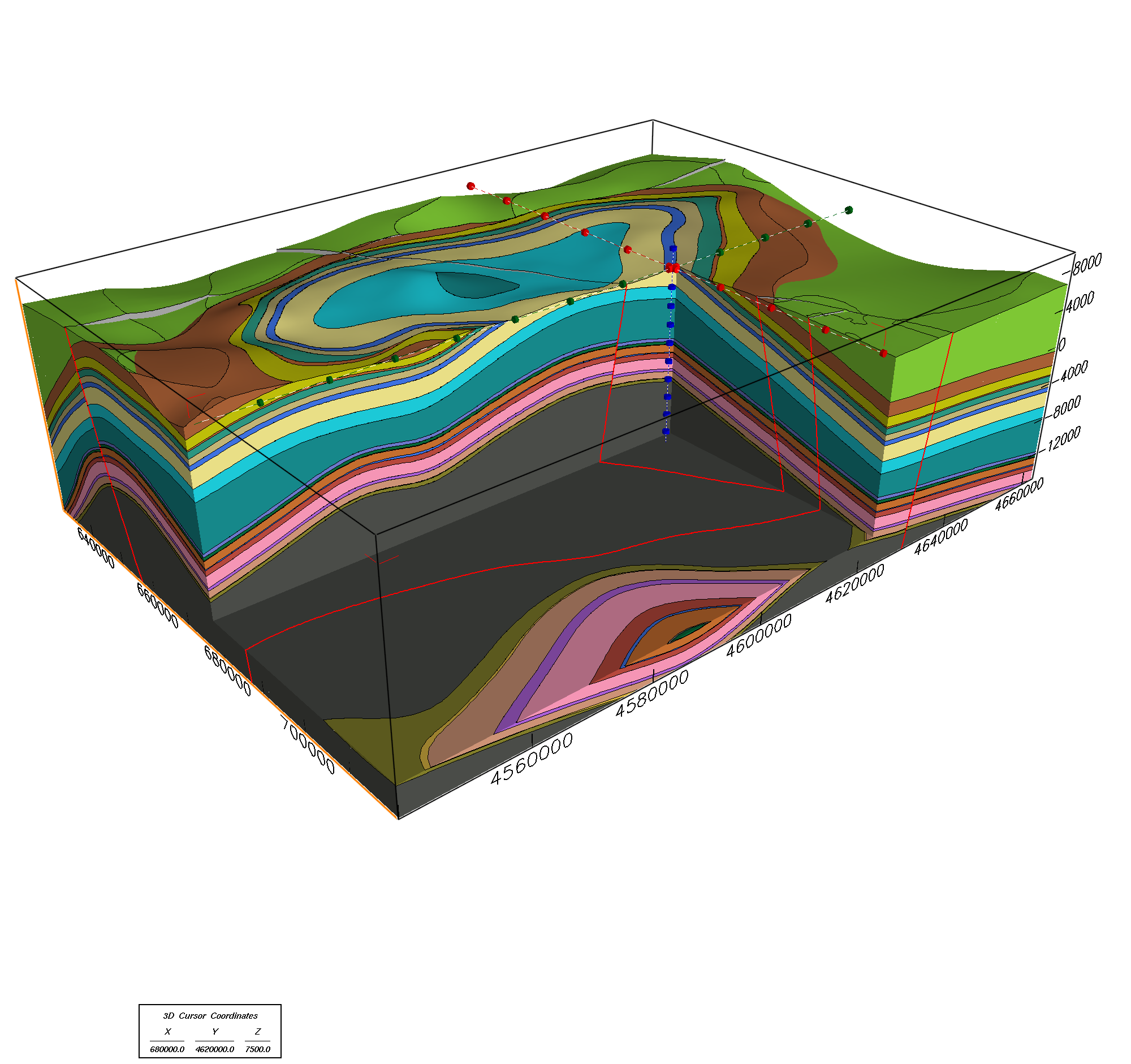
|
Input Surfaces for Slopes 3x 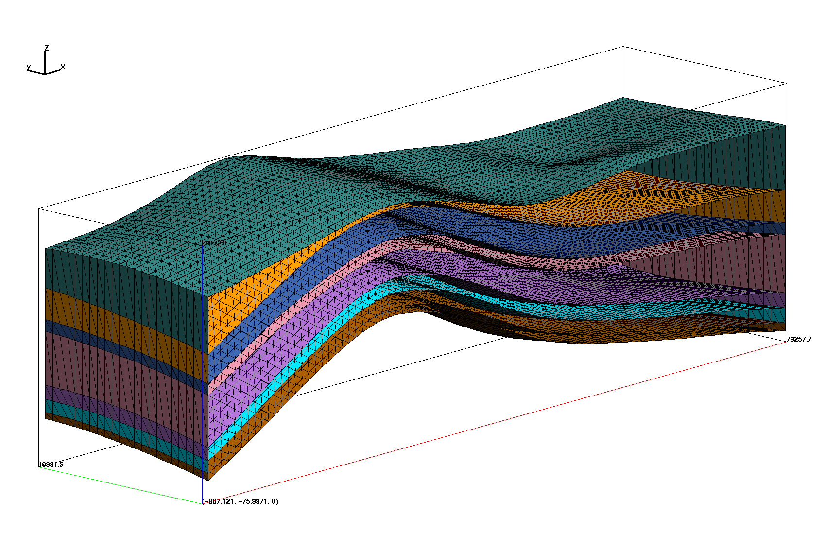
|
VoroCrust Mesh for Shell 3x MANIFOLD 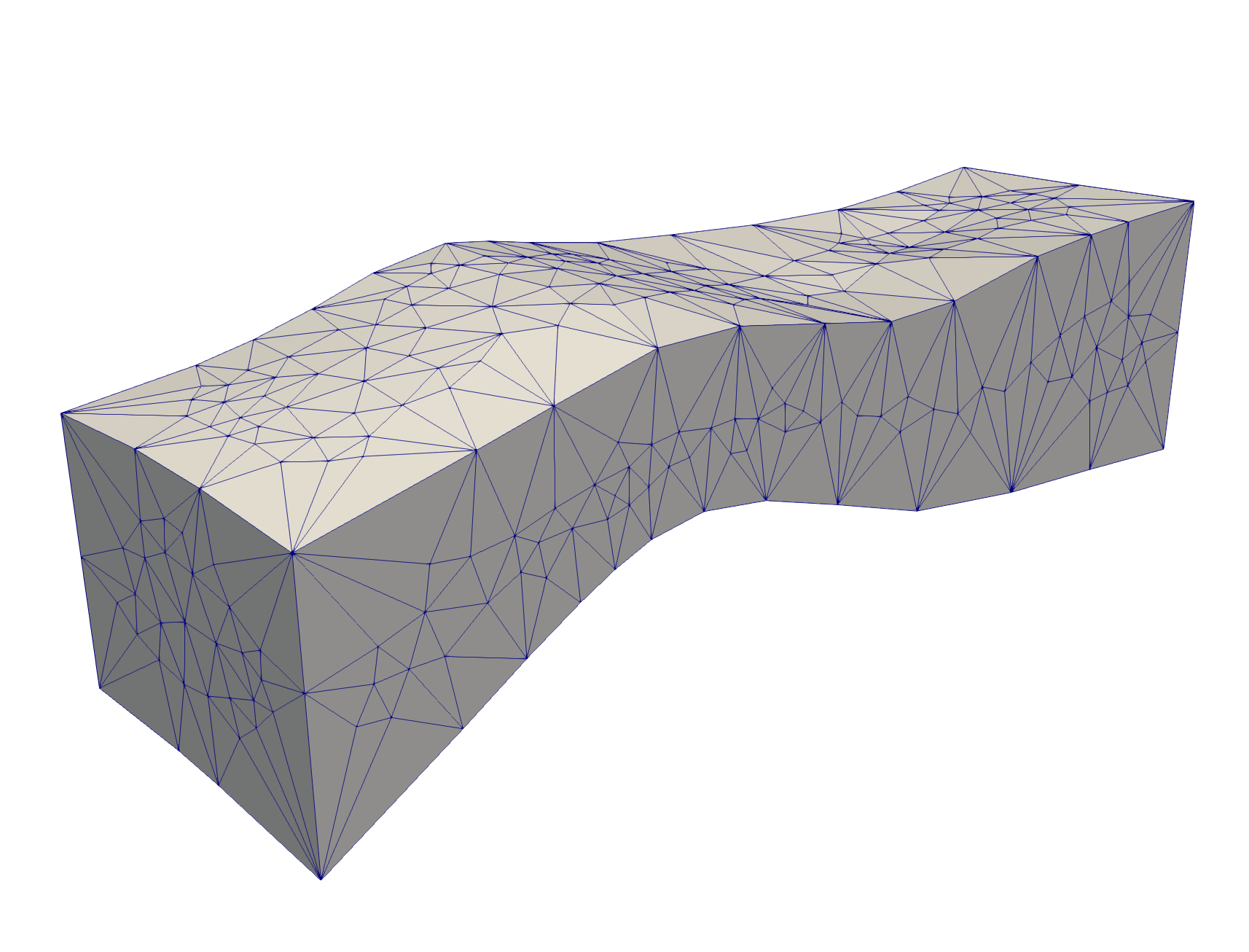
|
|
Input Surface from FEHM CO2 Incline MANIFOLD 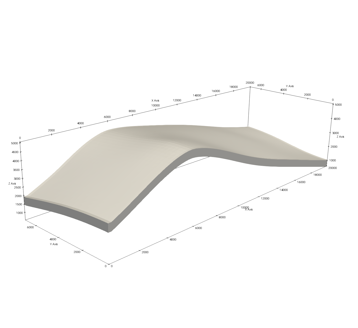
|
VoroCrust Mesh for CO2 Incline 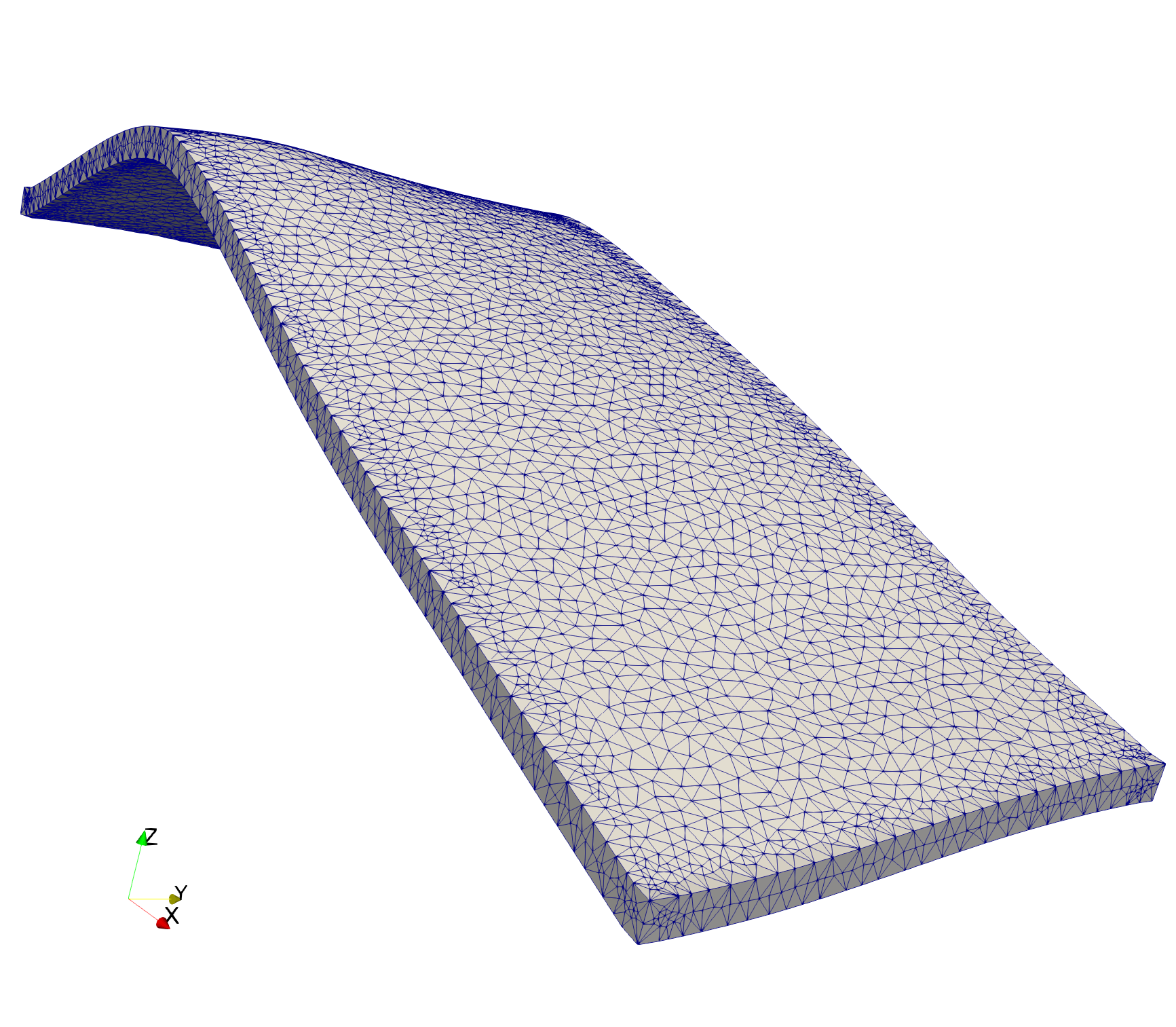
|
These 2D fractures were generated using dfnWorks. The fractures were put into a bounding cube for meshing with VoroCrust.
There are 2 fractures tests, a single fracture and a set of 4 fractures.
There are 2 versions of the bounding box, one is connected to fractures, the other is not.
Gallery of VoroCrust Meshing Gallery

Images are clipped from the front to show the internal boundaries.

Note: There are currenty no VoroCrust solutions for any of the hanging or floating fractures.
|
Input Surface for 1 Hanging Fracture 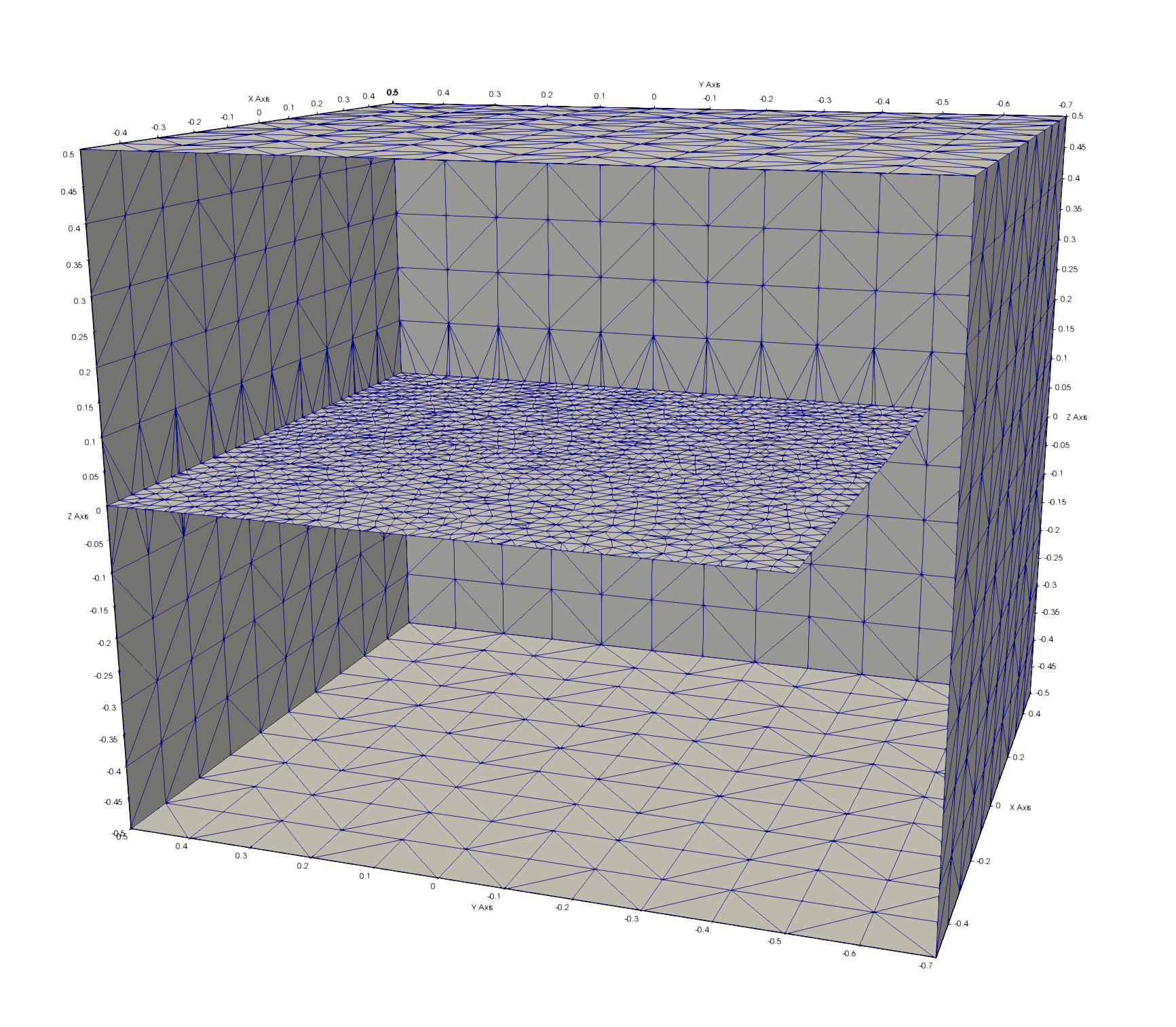
|
Input Surface for 4 Fractures 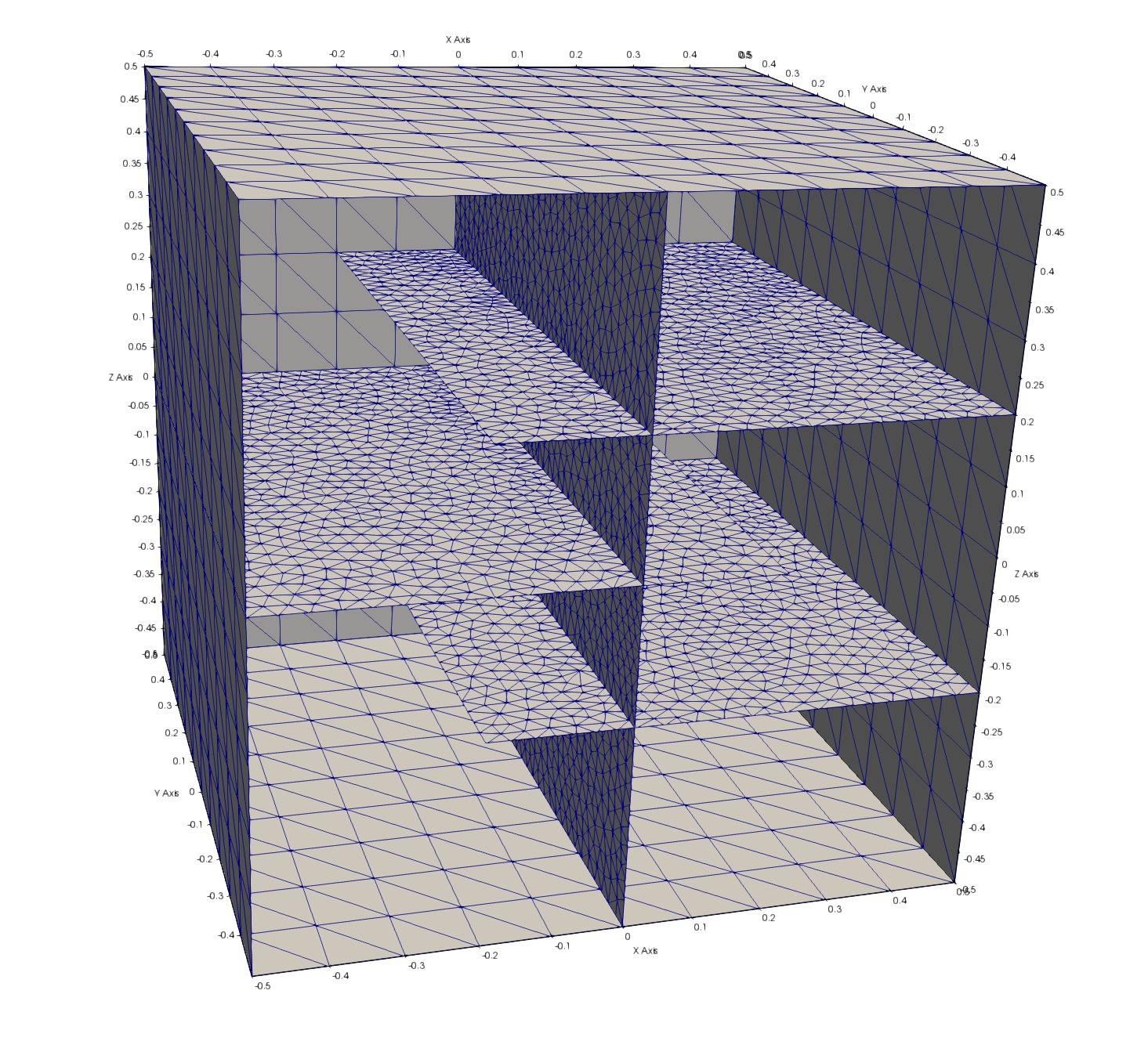
|