| Version |
Scope |
Finished |
Total |
| Fine Deep Mesh |
| V3.2.0_C.1 |
Area C Single Polygon 06 |
Nov 2013 |
229,284 Nodes and |
435,968 Cells |
| V3.2.0_C.2 |
Area C Single Polygon 31 |
Nov 2013 |
330,660 Nodes and |
637,184 Cells |
| V3.2.0_C.3 |
Area C Single Polygon 44 |
Nov 2013 |
159,588 Nodes and |
301,824 Cells |
| V3.2.0_C.4 |
Area C Single Polygon 45 |
Nov 2013 |
698,148 Nodes and |
1,358,208 Cells |
| V3.2.0_C.5 |
Area C Multiple Polygons "lobster+" |
Nov 2013 |
7,651,908 Nodes and |
15,057,664 Cells |
| Fine Mesh |
| V3.1.0_C.1.1 |
Area C Multiple Polygons "lobster+" |
July 2013 |
5,622,993 Nodes and |
11,034,624 Cells |
| V3.1.0_C.1 |
Area C Multiple Polygons "lobster" |
July 2013 |
5,242,753 Nodes and |
10,285,056 Cells |
| V3.1.0_C.0 |
Area C All Polygons |
July 2013 |
16,970,053 Nodes and |
33,441,792 Cells |
| V3.1.0 |
Area C Group 40 |
June 2013 |
1,404,657 Nodes and |
2,740,224 Cells |
| V3.0.2 |
Area C Single 06 with corners |
Nov 2013 |
168,489 Nodes and |
319,488 Cells |
| V3.0.1 |
Area C Single 40 with corners |
July 2013 |
311,273 Nodes and |
602,112 Cells |
| V3.0.0 |
Area C Single 40 |
June 2013 |
311,273 Nodes and |
602,112 Cells |
| V2.0.0 |
Area C Single 40 |
June 2013 |
311,273 Nodes and |
602,112 Cells |
| V1.0.0 |
Area C Single 40 Prototype |
May 2013 |
51,344 Nodes and |
94,080 Cells |
| Test Mesh |
| Test1 |
Column with flat top |
Oct 2013 |
291 Nodes and |
96 Cells |
| Test2 |
Flat top, deep mesh |
Nov 2013 |
396 Nodes and |
131 Cells |
| Test3 |
Coordiante change, deep mesh |
Feb 2014 |
396 Nodes and |
131 Cells |
| Test4 |
Upper organic layer = 0.10 m |
Mar 2014 |
387 Nodes and |
128 Cells |
| Test5 |
No moss layer, upper organic 8cm |
Mar 2013 |
378 Nodes and |
125 Cells |
| Test6 |
Upper organic layer = 0.06 m |
Mar 2014 |
381 Nodes and |
126 Cells |
| Test7 |
No moss layer, upper organic 4cm |
Mar 2013 |
372 Nodes and |
123 Cells |
| Test8 |
Upper organic layer = 0.16 m |
Mar 2014 |
393 Nodes and |
130 Cells |
| Test9 |
No moss layer, upper organic 14cm |
Mar 2013 |
384 Nodes and |
127 Cells |
These meshes were developed in support of the Arctic Next Generation Ecosystem Experiment (NGEE-Arctic) Project and LANL Laboratory Directed project LDRD20120068DR. These two projects share a need for high quality computational meshes for use in fine-scale modeling of thermal hydrology in ice-wedge polygon landscapes.
The input data is organized into a set of files that contain data extracted from lidar data. The data set is canonized by Chandana Gangodagamage and organized into files. One file contains ground surface elevations for the area and several files contain reference coordinates for polygons separated into one file per polygon.
The conceptual design for these models are based on observations and data collected for the Arctic project. The top
surface uses elevation and image data of tundra areas A, B, and C. The subsurface layers and ice_wedges are derived
from the top elevations and are generalizations of field observations.
The top surfaces of these models are polygonal tundra shapes and elevations derived from actual LIDAR data sets.
The top surface polygon shapes and elevations are created and provided as input for the meshing.
The subsurface layers of the models are based on descriptions and observations of core data. The layers represented are
moss (part of the active layer), organic, and mineral. These layers are split into layers within and below the permafrost.
As observed by Joel Rowland referring to the core data from ORL (of 30 cm or less); they have " ... a sequence of an upper organic layer (includes "moss" or live vegation), a mineral layer, then a deeper organic layer. ... the average thickness of the layers were: 11 cm, 11 cm, and 7.5 (biased by one core with a thick lower organic layer)."
The ice wedge shapes follow the tundra polygon shape and have a constant rim width and constant depth to end point. The top of the ice wedge tops start below the permafrost boundary.
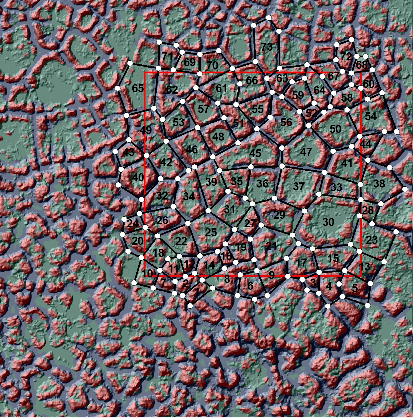
Polygon identification numbers and node locations are shown on the image below for the NGEE extensive site-C. Image is provided by Chandana Gangodagamage
| V3.2.0_C.1 Mesh (6 layers) : 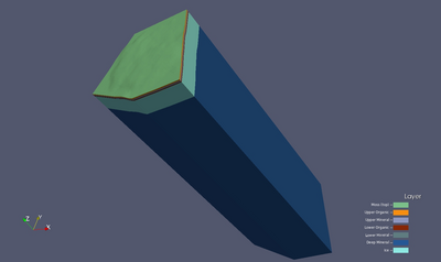 Version 3.2.C.1 runs the Version 3.C.# extending the deep mineral layer (layer 6) to -45 deep. This mesh is 3D based on single polygon #6 generated using LiDAR data set (area C). This mesh follows the criteria listed in the Mesh Input Parameters below. The mesh has 1 moss layer, 2 organic layers, and 3 mineral layers with a flat bottom. The Ice Wedge starts at the top of the mineral layers and is aprox 2.8 meters long. The convention of layer order numbering is from top to bottom. Two Exodus II mesh files are written, one multi-material with ice, and one single material. Version 3.2.C.1 runs the Version 3.C.# extending the deep mineral layer (layer 6) to -45 deep. This mesh is 3D based on single polygon #6 generated using LiDAR data set (area C). This mesh follows the criteria listed in the Mesh Input Parameters below. The mesh has 1 moss layer, 2 organic layers, and 3 mineral layers with a flat bottom. The Ice Wedge starts at the top of the mineral layers and is aprox 2.8 meters long. The convention of layer order numbering is from top to bottom. Two Exodus II mesh files are written, one multi-material with ice, and one single material.
|
| V3.2.0_C.2 Mesh (6 layers) : 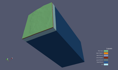 Version 3.2.C.2 runs the Version 3.C.# extending the deep mineral layer (layer 6) to -45 deep. This mesh is 3D based on single polygon #31 generated using LiDAR data set (area C). This mesh follows the criteria listed in the Mesh Input Parameters below. The mesh has 1 moss layer, 2 organic layers, and 3 mineral layers with a flat bottom. The Ice Wedge starts at the top of the mineral layers and is aprox 2.8 meters long. The convention of layer order numbering is from top to bottom. Two Exodus II mesh files are written, one multi-material with ice, and one single material. Version 3.2.C.2 runs the Version 3.C.# extending the deep mineral layer (layer 6) to -45 deep. This mesh is 3D based on single polygon #31 generated using LiDAR data set (area C). This mesh follows the criteria listed in the Mesh Input Parameters below. The mesh has 1 moss layer, 2 organic layers, and 3 mineral layers with a flat bottom. The Ice Wedge starts at the top of the mineral layers and is aprox 2.8 meters long. The convention of layer order numbering is from top to bottom. Two Exodus II mesh files are written, one multi-material with ice, and one single material.
|
| V3.2.0_C.3 Mesh (6 layers) : 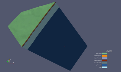 Version 3.2.C.3 runs the Version 3.C.# extending the deep mineral layer (layer 6) to -45 deep. This mesh is 3D based on single polygon #44 generated using LiDAR data set (area C). This mesh follows the criteria listed in the Mesh Input Parameters below. The mesh has 1 moss layer, 2 organic layers, and 3 mineral layers with a flat bottom. The Ice Wedge starts at the top of the mineral layers and is aprox 2.8 meters long. The convention of layer order numbering is from top to bottom. Two Exodus II mesh files are written, one multi-material with ice, and one single material. Version 3.2.C.3 runs the Version 3.C.# extending the deep mineral layer (layer 6) to -45 deep. This mesh is 3D based on single polygon #44 generated using LiDAR data set (area C). This mesh follows the criteria listed in the Mesh Input Parameters below. The mesh has 1 moss layer, 2 organic layers, and 3 mineral layers with a flat bottom. The Ice Wedge starts at the top of the mineral layers and is aprox 2.8 meters long. The convention of layer order numbering is from top to bottom. Two Exodus II mesh files are written, one multi-material with ice, and one single material.
|
| V3.2.0_C.4 Mesh (6 layers) : 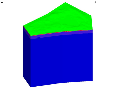 Version 3.2.C.4 runs the Version 3.C.# extending the deep mineral layer (layer 6) to -45 deep. This mesh is 3D based on single polygon #45 generated using LiDAR data set (area C). This mesh follows the criteria listed in the Mesh Input Parameters below. The mesh has 1 moss layer, 2 organic layers, and 3 mineral layers with a flat bottom. The Ice Wedge starts at the top of the mineral layers and is aprox 2.8 meters long. The convention of layer order numbering is from top to bottom. Two Exodus II mesh files are written, one multi-material with ice, and one single material. Version 3.2.C.4 runs the Version 3.C.# extending the deep mineral layer (layer 6) to -45 deep. This mesh is 3D based on single polygon #45 generated using LiDAR data set (area C). This mesh follows the criteria listed in the Mesh Input Parameters below. The mesh has 1 moss layer, 2 organic layers, and 3 mineral layers with a flat bottom. The Ice Wedge starts at the top of the mineral layers and is aprox 2.8 meters long. The convention of layer order numbering is from top to bottom. Two Exodus II mesh files are written, one multi-material with ice, and one single material.
|
| V3.2.0_C.5 Mesh (6 layers) : 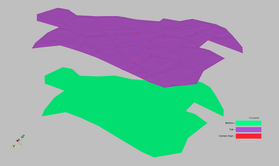 Version 3.2.C.5 runs the Version 3.C.# extending the deep mineral layer (layer 6) to -45 deep. This mesh is 3D based on multiple polygons ##6, 8, 9, 19, 21, 25, 27, 29, 31, 34, 35, 36, 37, 39, 45, 47, 50, 56 generated using LiDAR data set (area C). This mesh follows the criteria listed in the Mesh Input Parameters below. The mesh has 1 moss layer, 2 organic layers, and 3 mineral layers with a flat bottom. The Ice Wedge starts at the top of the mineral layers and is aprox 2.8 meters long. The convention of layer order numbering is from top to bottom. Two Exodus II mesh files are written, one multi-material with ice, and one single material. Version 3.2.C.5 runs the Version 3.C.# extending the deep mineral layer (layer 6) to -45 deep. This mesh is 3D based on multiple polygons ##6, 8, 9, 19, 21, 25, 27, 29, 31, 34, 35, 36, 37, 39, 45, 47, 50, 56 generated using LiDAR data set (area C). This mesh follows the criteria listed in the Mesh Input Parameters below. The mesh has 1 moss layer, 2 organic layers, and 3 mineral layers with a flat bottom. The Ice Wedge starts at the top of the mineral layers and is aprox 2.8 meters long. The convention of layer order numbering is from top to bottom. Two Exodus II mesh files are written, one multi-material with ice, and one single material.
|
| V3.C.1.1 Mesh (6 layers) : 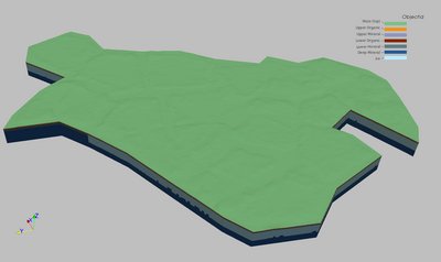 Version 3.C.1.1 runs the Version 3.1 mesh with the polygons of V3.C.1 adding polygon #56. This mesh is 3D based on multiple polygons ##6, 8, 9, 19, 21, 25, 27, 29, 31, 34, 35, 36, 37, 39, 45, 47, 50, 56 generated using LiDAR data set (area C). This mesh follows the criteria listed in the Mesh Input Parameters below. The mesh has 1 moss layer, 2 organic layers, and 3 mineral layers with a flat bottom. The Ice Wedge starts at the top of the mineral layers and is aprox 2.8 meters long. The convention of layer order numbering is from top to bottom. Two Exodus II mesh files are written, one multi-material with ice, and one single material. Version 3.C.1.1 runs the Version 3.1 mesh with the polygons of V3.C.1 adding polygon #56. This mesh is 3D based on multiple polygons ##6, 8, 9, 19, 21, 25, 27, 29, 31, 34, 35, 36, 37, 39, 45, 47, 50, 56 generated using LiDAR data set (area C). This mesh follows the criteria listed in the Mesh Input Parameters below. The mesh has 1 moss layer, 2 organic layers, and 3 mineral layers with a flat bottom. The Ice Wedge starts at the top of the mineral layers and is aprox 2.8 meters long. The convention of layer order numbering is from top to bottom. Two Exodus II mesh files are written, one multi-material with ice, and one single material.
|
| V3.C.1 Mesh (6 layers) : 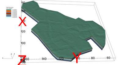 Version 3.C.1 runs the Version 3.1 with different number of polygons to create the mesh. This mesh is 3D based on multiple polygons ##6, 8, 9, 19, 21, 25, 27, 29, 31, 34, 35, 36, 37, 39, 45, 47, 50 generated using LiDAR data set (area C). This mesh follows the criteria listed in the Mesh Input Parameters below. The mesh has 1 moss layer, 2 organic layers, and 3 mineral layers with a flat bottom. The Ice Wedge starts at the top of the mineral layers and is aprox 2.8 meters long. The convention of layer order numbering is from top to bottom. Two Exodus II mesh files are written, one multi-material with ice, and one single material. Version 3.C.1 runs the Version 3.1 with different number of polygons to create the mesh. This mesh is 3D based on multiple polygons ##6, 8, 9, 19, 21, 25, 27, 29, 31, 34, 35, 36, 37, 39, 45, 47, 50 generated using LiDAR data set (area C). This mesh follows the criteria listed in the Mesh Input Parameters below. The mesh has 1 moss layer, 2 organic layers, and 3 mineral layers with a flat bottom. The Ice Wedge starts at the top of the mineral layers and is aprox 2.8 meters long. The convention of layer order numbering is from top to bottom. Two Exodus II mesh files are written, one multi-material with ice, and one single material.
|
| V3.C.0 Mesh (6 layers) : 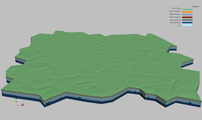 Version 3.C.1 runs the Version 3.1 with all area C polygons. This mesh is 3D based on polygons generated using LiDAR data set (area C). This mesh follows the criteria listed in the Mesh Input Parameters below. The mesh has 1 moss layer, 2 organic layers, and 3 mineral layers with a flat bottom. The Ice Wedge starts at the top of the mineral layers and is aprox 2.8 meters long. The convention of layer order numbering is from top to bottom. Two Exodus II mesh files are written, one multi-material with ice, and one single material. Version 3.C.1 runs the Version 3.1 with all area C polygons. This mesh is 3D based on polygons generated using LiDAR data set (area C). This mesh follows the criteria listed in the Mesh Input Parameters below. The mesh has 1 moss layer, 2 organic layers, and 3 mineral layers with a flat bottom. The Ice Wedge starts at the top of the mineral layers and is aprox 2.8 meters long. The convention of layer order numbering is from top to bottom. Two Exodus II mesh files are written, one multi-material with ice, and one single material.
|
| V3.1 Mesh (6 layers) : 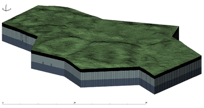 Version 3.1 is a modification of the Version 3 mesh which adds neighboring polygons to the polygon #40. This mesh is 3D based on multiple polygons #32, 40, 42, 43, 49 generated using LiDAR data set (area C). This mesh follows the criteria listed in the Mesh Input Parameters below. The mesh has 1 moss layer, 2 organic layers, and 3 mineral layers with a flat bottom. The Ice Wedge starts at the top of the mineral layers and is aprox 2.8 meters long. The convention of layer order numbering is from top to bottom. Two Exodus II mesh files are written, one multi-material with ice, and one single material. Version 3.1 is a modification of the Version 3 mesh which adds neighboring polygons to the polygon #40. This mesh is 3D based on multiple polygons #32, 40, 42, 43, 49 generated using LiDAR data set (area C). This mesh follows the criteria listed in the Mesh Input Parameters below. The mesh has 1 moss layer, 2 organic layers, and 3 mineral layers with a flat bottom. The Ice Wedge starts at the top of the mineral layers and is aprox 2.8 meters long. The convention of layer order numbering is from top to bottom. Two Exodus II mesh files are written, one multi-material with ice, and one single material.
|
| V3.0.2 Mesh (6 layers) with corners: 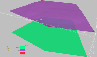 Version 3.0.2 is a run of mesh Version 3.0.1 with the polygon #06. No other changes to Version 3.0.1 were made. Version 3.0.2 is a run of mesh Version 3.0.1 with the polygon #06. No other changes to Version 3.0.1 were made.
|
| V3.0.1 Mesh (6 layers) with corners: 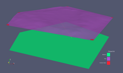 Version 3.0.1 is a modification of the Version 3.0 mesh which adds corner faces to the exodus file. This version has a correction to file write_exo.lgi and now has two additional layers for corner and top faces. The following are additional faces that were added to the V3.0.0: layer 7 -> corner side faces layer 8 -> corner top faces Version 3.0.1 is a modification of the Version 3.0 mesh which adds corner faces to the exodus file. This version has a correction to file write_exo.lgi and now has two additional layers for corner and top faces. The following are additional faces that were added to the V3.0.0: layer 7 -> corner side faces layer 8 -> corner top faces
|
| V3.0 Mesh (6 layers) : 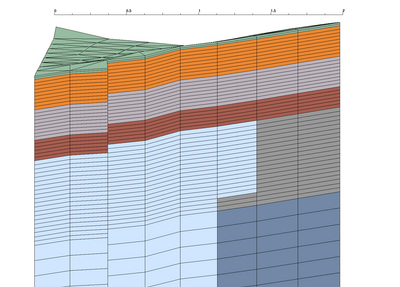 Version 3 is a modification of the Version 2 mesh which adds a third mineral layer between upper and lower organic layers. This mesh design will be used for the version 01 with multiple polygons. This mesh is 3D based on single polygon #40 generated using LiDAR data set (area C). This mesh follows the criteria listed in the Mesh Input Parameters below. The mesh has 1 moss layer, 2 organic layers, and 3 mineral layers with a flat bottom. The Ice Wedge starts at the top of the mineral layers and is aprox 2.8 meters long. The convention of layer order numbering is from top to bottom. Two Exodus II mesh files are written, one multi-material with ice, and one single material. Version 3 is a modification of the Version 2 mesh which adds a third mineral layer between upper and lower organic layers. This mesh design will be used for the version 01 with multiple polygons. This mesh is 3D based on single polygon #40 generated using LiDAR data set (area C). This mesh follows the criteria listed in the Mesh Input Parameters below. The mesh has 1 moss layer, 2 organic layers, and 3 mineral layers with a flat bottom. The Ice Wedge starts at the top of the mineral layers and is aprox 2.8 meters long. The convention of layer order numbering is from top to bottom. Two Exodus II mesh files are written, one multi-material with ice, and one single material.
|
| V2.0 Mesh (5 layers) : 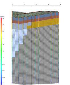 Version 2 is a modification of the Version 1 mesh which is a 3D mesh polygon based on single polygon #40 generated using LiDAR data set (area C). This mesh has changes to V1 based on the Mesh Input Parameters below. It has increased vertical resolution and a flat bottom. The convention of layer order was also changed so that numbering is from top to bottom. Two Exodus II mesh files are written, one multi-material with ice, and one single material. Version 2 is a modification of the Version 1 mesh which is a 3D mesh polygon based on single polygon #40 generated using LiDAR data set (area C). This mesh has changes to V1 based on the Mesh Input Parameters below. It has increased vertical resolution and a flat bottom. The convention of layer order was also changed so that numbering is from top to bottom. Two Exodus II mesh files are written, one multi-material with ice, and one single material.
|
| V1.0 Mesh (prototype): 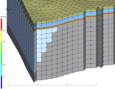 This is prototype 3D mesh of a wedge polygon based on polygon #40 generated using LiDAR data set. Two Exodus II mesh files are written, one multi-material, and one single material. This is prototype 3D mesh of a wedge polygon based on polygon #40 generated using LiDAR data set. Two Exodus II mesh files are written, one multi-material, and one single material.
|
| Test 1 : 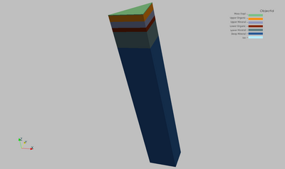 3D column with flat top. This mesh is 3D based on a polygon generated using 3 points data set. 3D column with flat top. This mesh is 3D based on a polygon generated using 3 points data set.
The mesh has 1 moss layer, 2 organic layers, and 3 mineral layers with a flat top and bottom. Bottom is at -1.
The convention of layer order numbering is from top to bottom.
Two Exodus II mesh files are written, one multi-material, and one single material. |
| Test 2 : 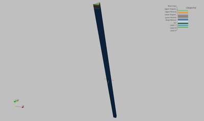 3D column with flat top. This mesh is 3D based on a polygon generated using 3 points data set. 3D column with flat top. This mesh is 3D based on a polygon generated using 3 points data set.
The mesh has 1 moss layer, 2 organic layers, and 3 mineral layers with a flat top and bottom. Bottom is at -45.
The convention of layer order numbering is from top to bottom.
Two Exodus II mesh files are written, one multi-material, and one single material. |
| Test 3 : 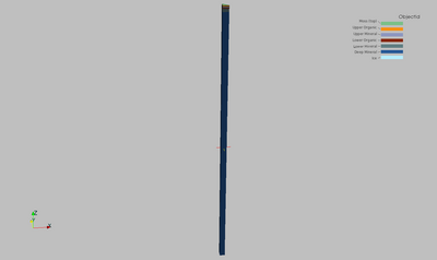 Same as 2, but with different coordinates for 3 point data set. Same as 2, but with different coordinates for 3 point data set.
|
| Test 4 : 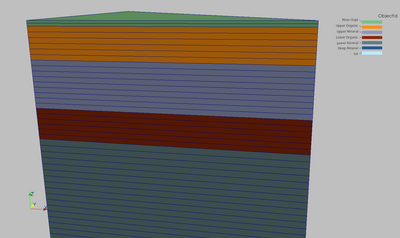 3D column with flat top. This mesh is 3D based on a polygon generated using 3 points data set. 3D column with flat top. This mesh is 3D based on a polygon generated using 3 points data set.
Upper organic layer thickness is changed to 0.12 m (6 cells). |
| Test 5 : 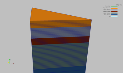 Moss layer removed. The layer numbering starts from 2 - upper organic layer. Moss layer removed. The layer numbering starts from 2 - upper organic layer.
Upper organic layer thickness is changed to 0.10 m (4 cells). |
| Test 6 : 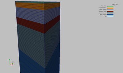 3D column with flat top. This mesh is 3D based on a polygon generated using 3 points data set. 3D column with flat top. This mesh is 3D based on a polygon generated using 3 points data set.
Upper organic layer thickness is changed to 0.08 m (4 cells). |
| Test 7 : 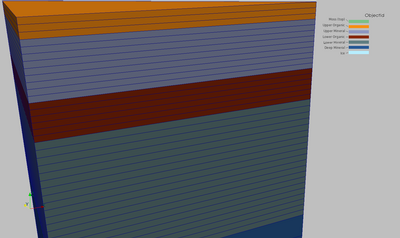 Moss layer removed. The layer numbering starts from 2 - upper organic layer. Moss layer removed. The layer numbering starts from 2 - upper organic layer.
Upper organic layer thickness is changed to 0.06 m (3 cells). |
| Test 8 : 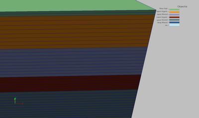 3D column with flat top. This mesh is 3D based on a polygon generated using 3 points data set. 3D column with flat top. This mesh is 3D based on a polygon generated using 3 points data set.
Upper organic layer thickness is changed to 0.16 m (8 cells). |
| Test 9 : 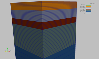 Moss layer removed. The layer numbering starts from 2 - upper organic layer. Moss layer removed. The layer numbering starts from 2 - upper organic layer.
Upper organic layer thickness is changed to 0.14 m (7 cells). |